Think your Kohler 7000 series engine has a dead battery or a fried starter? It might just need a valve adjustment. This guide walks you through the exact Kohler 7000 series valve adjustment specs, step-by-step procedure, and the sneaky failure modes that fool even experienced mechanics. Stick around — the ACR section alone could save you $200 in misdiagnosed parts.
What Makes the Kohler 7000 Series Tick
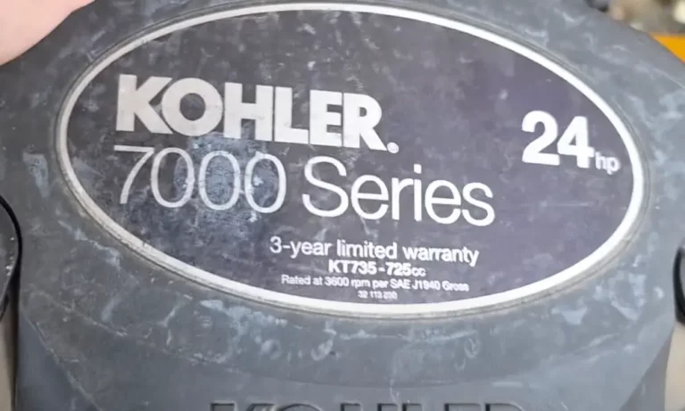
The Kohler 7000 Series covers six engine models: KT715, KT725, KT730, KT735, KT740, and KT745. They’re V-twin, overhead-valve, four-stroke engines that power a massive chunk of residential and commercial lawn tractors across the country.
Here’s the quick spec breakdown you need before touching anything:
| Specification | Details |
|---|---|
| Configuration | V-Twin, OHV, Four-Stroke, Air-Cooled |
| Displacement (KT715–KT730) | 725 cc (44.2 cu in) |
| Displacement (KT735–KT745) | 747 cc (45.6 cu in) |
| Bore Diameter | 3.27 in (83 mm) |
| Oil Capacity | 2.0 U.S. quarts |
| Spark Plug Gap | 0.030 in (0.76 mm) |
| Max Safe Operating Angle | 25 degrees |
The overhead-valve design puts the valves directly above the combustion chamber. That’s great for power and efficiency — but it means precise valve clearance isn’t optional. It’s the difference between a smooth-running engine and an expensive rebuild.
Why Valve Clearance Actually Matters
Metal expands when it gets hot. Every piece inside your engine — the aluminum head, steel valves, cast-iron liner, and push rods — expands at a different rate. That’s why you set clearance when the engine is stone cold.
When you fire up the engine, those components grow toward each other. The small gap you set beforehand closes down to a paper-thin film of pressurized oil. That’s exactly what you want.
Too tight: Thermal expansion forces the valve open during combustion. Hot gases blast past the unseated valve face. The valve can’t shed heat into the head, overheats, warps, and burns. You’re looking at a full cylinder head replacement.
Too loose: The valve opens late and closes early. You lose power, and the rocker arm slams the valve tip violently on every cycle. That metallic ticking you hear? That’s parts wearing out fast. Worse, loose clearance kills the ACR system — which we’ll cover next.
The Automatic Compression Release System Explained
The ACR is one of the cleverest things Kohler ever built into these engines — and one of the most misunderstood.
A 747 cc V-twin builds enormous compression pressure. Without help, your stock 12-volt starter motor and lead-acid battery couldn’t turn it over. The ACR solves this problem with a centrifugal flyweight mechanism built directly into the camshaft.
How It Works
- At cranking speed (below ~600 RPM): A spring holds the flyweight inward. A tiny protrusion on the camshaft bumps the exhaust lifter during the compression stroke, cracking the exhaust valve open just a fraction. This bleeds off compression, letting the starter spin the engine easily.
- Once the engine fires: RPM jumps instantly. Centrifugal force swings the flyweight outward. The protrusion drops flush with the cam lobe. The exhaust valve seals completely, and the engine runs at full compression.
The Critical Link Between ACR and Valve Clearance
The ACR bump is tiny — measured in thousandths of an inch. It only works if the valve train has the correct amount of slack.
If exhaust valve clearance grows past 0.006 inches, the ACR bump gets swallowed up by that extra gap. The rocker arm tilts slightly but never contacts the valve tip. The exhaust valve stays shut. The starter tries to crank a full-compression engine and stalls immediately.
This single mechanical fact explains why countless operators replace perfectly good batteries, starters, and solenoids when the real fix is a five-minute valve adjustment.
Exact Kohler 7000 Series Valve Clearance Specs
Set these only on a completely cold engine. No exceptions.
| Valve Type | Clearance (Inches) | Clearance (Millimeters) |
|---|---|---|
| Intake Valve | 0.004 – 0.006 in | 0.101 – 0.152 mm |
| Exhaust Valve | 0.004 – 0.006 in | 0.101 – 0.152 mm |
Both valves use the same spec. Some older engines ran looser exhaust clearances to account for extra heat, but current Kohler documentation for the KT Series is clear: 0.004 to 0.006 inches for both. Stick to it.
Your target setting during adjustment is 0.005 inches — the midpoint of the range.
Critical Torque Specs for Reassembly
| Component | Torque Value |
|---|---|
| Valve Adjuster Set Screw (T-25 Torx) | 70 in-lbs |
| Rocker Arm Pivot Stud | 100 in-lbs |
| Spark Plug | 20 ft-lbs |
| Composite Valve Cover (hex-flange screws) | 80 in-lbs |
| Composite Valve Cover (Torx pan-head screws) | 55 in-lbs |
| Stamped Steel Valve Cover | 120 in-lbs |
| Cylinder Head Bolts — Stage 1 | 200 in-lbs |
| Cylinder Head Bolts — Stage 2 | 370 in-lbs |
Over-torquing composite plastic valve covers will crack them. Use a proper inch-pound torque wrench here, not a gut-feel grunt.
Safety Prep Before You Touch Anything
Don’t skip this part. It takes three minutes and protects both you and the engine.
- Park on a completely level surface
- Engage the parking brake and shift to neutral
- Pull the ignition key
- Disconnect both spark plug leads and ground them away from the terminals
- Disconnect the negative battery cable
- Let the engine sit until it’s fully cold — overnight is ideal, minimum several hours in the shade
Cold adjustment isn’t just a suggestion. A warm engine gives false readings because thermal expansion tightens the gaps. You’d set the valves too loose, then wonder why the engine barely starts.
Remove the engine shrouds and cooling bonnet using an 8mm or 10mm socket. This exposes the valve covers and also gives you a chance to check the cooling fins for packed debris — a major cause of overheating failures.
Valve Cover Types: Know Which One You Have
The Kohler 7000 Series uses two distinct valve cover designs, and they need completely different handling.
Stamped Steel Covers:
Found on older engines. These covers warp under heat and over-torquing. They seal against liquid RTV sealant and require 120 in-lbs of torque. They’re notorious for weeping oil onto hot exhaust manifolds over time.
Composite Plastic Covers:
The current standard. These use a thick rubber O-ring seated in a groove — no RTV needed. They require only 55 to 80 in-lbs depending on fastener type. Crack one by over-torquing it, and you’ll be ordering a replacement immediately.
If your older engine leaks chronically from warped steel covers, Kohler’s upgrade kit (Part Number 24 755 141-S) retrofits composite covers onto older engines. Industry professionals recommend it highly for a permanent fix.
Step-by-Step Kohler 7000 Series Valve Adjustment Procedure
Step 1 — Find Top Dead Center on the Compression Stroke
This is the most important step. You must adjust valves only on the compression stroke — not the exhaust stroke. If you adjust at the wrong TDC, both clearances will be massively off and the engine won’t run.
Here’s how to nail it every time:
- Remove both spark plugs with a 5/8-inch socket. This relieves cylinder pressure and lets the flywheel spin freely by hand.
- Remove the valve cover on cylinder one.
- Rotate the flywheel clockwise by hand. Watch the rocker arms carefully.
- Identify the sequence: exhaust valve opens and closes → intake valve opens and closes → compression stroke begins.
- The moment the intake valve closes completely, insert a long wooden dowel or pencil gently into the spark plug hole. Rest it lightly on the piston crown. Never use metal — it scratches the piston and damages threads.
- Continue rotating slowly. The dowel rises as the piston climbs.
- The instant the dowel stops moving and reverses — that’s TDC on the compression stroke. Stop there.
At this point, both cam lobes present their flat base circles to the lifters. Both valves are completely closed and under zero spring tension. This is the only correct position for adjustment.
Step 2 — Measure the Clearance
Slide a 0.005-inch feeler gauge into the gap between the rocker arm’s striking pad and the valve stem tip.
The correct feel: slight but distinct drag — like pulling a piece of heavy paper from under a moderately heavy book. Not tight. Not sloppy. Slight drag.
- Gauge won’t enter or requires heavy force: Too tight
- Gauge falls through with zero resistance: Too loose
- Slight drag: Correct — move to the next valve
Step 3 — Make the Adjustment
- Place a 1/2-inch closed-end wrench on the outer adjuster nut to hold it stationary.
- Insert a T-25 Torx bit into the center set screw and turn counterclockwise to loosen it.
- With the 0.005-inch gauge still in the gap, rotate the outer nut:
- Clockwise → tightens clearance
- Counterclockwise → loosens clearance
- Adjust until you feel that slight drag on the gauge.
- Hold the outer nut absolutely still with your wrench.
- Torque the center set screw to exactly 70 in-lbs using an inch-pound torque wrench.
- Re-check the clearance with the feeler gauge. Tightening the set screw often shifts the adjustment slightly.
- If the drag changed, loosen the set screw and repeat until the final torqued position yields the correct feel.
Repeat this process for both the intake and exhaust valves on cylinder one.
Step 4 — Position Cylinder Two
Per the official Kohler service documentation, rotate the crankshaft 270 degrees counterclockwise (viewed from the PTO end) to bring cylinder two to TDC on its compression stroke.
Alternatively, repeat the visual method: watch for the intake valve to fully close, insert the wooden dowel, and find the mechanical peak. Either method works. Once confirmed, adjust both valves on cylinder two using the same process.
Step 5 — Reassemble
- Clean the mating surfaces with a lint-free rag and mild solvent.
- Composite covers: Inspect the O-ring. If it’s flat, hard, or cracked, replace it. No RTV needed. Press the cover on and torque fasteners in a crisscross pattern to 55 or 80 in-lbs.
- Steel covers: Apply a continuous 1/16-inch bead of high-temp RTV around the entire flange, encircling each bolt hole. Torque to 120 in-lbs in a crisscross pattern.
- Reinstall spark plugs and torque to 20 ft-lbs.
- Reconnect spark plug wires and the negative battery cable.
Advanced Diagnostics: When Adjustment Doesn’t Solve It
The Bent Push Rod Problem
Discover a bent push rod — usually the intake side — and the temptation is to swap it out and call it done. Don’t.
A bent aluminum push rod is a mechanical fuse, not the root cause. It bent because the valve refused to open. The camshaft kept turning, force had nowhere to go, and the softest link gave way to protect the camshaft and rocker studs.
Two main reasons the valve gets stuck:
- Valve guide migration: Clogged cooling fins cause the head to overheat severely. The aluminum head expands faster than the pressed-in bronze valve guide. The guide loosens, the moving valve drags it out of its bore, and it jams the valve shut. This is a direct result of neglected cooling fin maintenance.
- Fuel varnish seizure: Stale ethanol-blended fuel left in the engine during storage deposits a sticky lacquer on the intake valve stem. Heat cures it into a hard carbon deposit that physically glues the stem inside the guide.
Putting in a new push rod without removing the head to fix the underlying cause means the new rod bends the second the starter engages.
Blown Head Gasket Symptoms
When a head gasket fails between the combustion chamber and the pushrod gallery, combustion gases don’t escape externally. They blast directly into the crankcase. The breather system can’t handle the pressure, and oil gets pushed out into the intake manifold and air filter housing.
Symptoms you’ll recognize immediately:
- Thick blue smoke from the exhaust
- Oil-soaked air filter
- Rapid oil consumption
- Significant power loss under load
Confirm it with a leak-down test. Inject compressed air into the cylinder. If you hear air rushing out through the open oil fill tube, you’ve got a blown head gasket that requires a full cylinder head removal to repair.
Single-Cylinder Running Misdiagnosis
A V-twin running on one cylinder shakes violently and bogs badly under load. Before you pull valve covers or heads, rule out ignition failure first.
With the engine at low idle, pull one spark plug boot using insulated pliers:
- Engine dies immediately: The other cylinder was the dead one
- Engine keeps running the same: The cylinder you just disconnected is the dead one
Ignition coils on these engines fail thermally over time. Also check the coil’s grounding wire — mice love chewing them during winter storage.
When installing a replacement coil, set the armature air gap between 0.008 and 0.012 inches using a feeler gauge, then torque the mounting screws to 35–55 in-lbs.
Long-Term Maintenance Schedule
Staying ahead of these failures costs almost nothing compared to fixing them after the fact.
- Every 25 hours: Service the air pre-cleaner
- Every 100 hours: Replace the main air filter element; change oil and filter
- Every 500 hours: Replace spark plugs (gap to 0.030 inches); check and adjust valve lash
- Annually: Remove the blower housing and shrouds; brush and blow all debris from the cooling fins. This one task prevents valve guide migration, head gasket failures, and bent push rods.
Keep oil between the low and full marks on the dipstick. Never operate the machine on slopes exceeding 25 degrees — beyond that angle, oil pools away from the pickup tube and the upper cylinder heads run dry within seconds.
FAQ: Kohler 7000 Series Valve Adjustment
What’s the correct valve clearance for the Kohler 7000 Series?
Both intake and exhaust valves require 0.004 to 0.006 inches, measured cold. Target 0.005 inches during adjustment for the best results.
Why does my engine barely turn over even with a new battery and starter?
Almost certainly a disabled ACR caused by excessive exhaust valve clearance. The starter can’t overcome full compression at cranking speed. Adjust the valves to spec and the problem disappears.
Does the exhaust valve need a different clearance than the intake?
No. Current Kohler documentation specifies 0.004–0.006 inches for both valves on all KT715 through KT745 models.
Why did my push rod bend?
The valve got stuck — either from fuel varnish seizing the stem in the guide, or from a valve guide that migrated out of position due to overheating. A new push rod won’t fix it. The head needs to come off to address the actual cause.
How often should I check the valve lash?
Every 500 hours per the official maintenance schedule. Check immediately if you notice hard starting, metallic ticking, backfiring, or power loss.
Can I adjust valves on a warm engine to save time?
No. Thermal expansion gives you false readings. You’ll set the gaps too loose, which disables the ACR and causes hard starting once the engine cools.
Why is oil coming out of my air filter?
A blown head gasket is pushing combustion gases into the crankcase, which forces oil out through the breather and into the intake. Confirm with a leak-down test, then replace the head gasket.
What’s the torque for the valve adjuster set screw?
70 inch-pounds using a T-25 Torx bit. Hold the outer adjuster nut completely still while torquing, then recheck the clearance — tightening the set screw often shifts the adjustment.
What torque do composite plastic valve covers need?
55 in-lbs for Torx pan-head screws, or 80 in-lbs for hex-flange screws. Over-torquing will crack the plastic housing.
My engine runs terribly on one cylinder. Is it the valves?
Not necessarily. Perform the single-cylinder ignition test first by pulling each spark plug boot at idle. Rule out a failed ignition coil or chewed grounding wire before opening up the valve train.