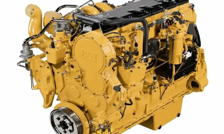
Finding the right sensor on a C15 can feel like a treasure hunt — especially when the engine has two completely different oil pressure sensors in two completely different places. This guide cuts through the confusion, shows you exactly where each sensor lives, and explains what happens when they fail. Stick around — the ACERT section alone could save you from a very expensive misdiagnosis.
Why the C15 Has Two Oil Pressure Sensors (And Why It Matters)
Most diesel engines have one oil pressure sensor. The Caterpillar C15 doesn’t follow that rule — at least not on later ACERT models.
Here’s the short version: Caterpillar built two distinct generations of the C15. The earlier non-ACERT engines (think 6NZ serial prefix) use one sensor monitoring the main oil gallery. The later ACERT engines — serial prefixes MXS, BXS, NXS, and SDP — added a second, completely separate sensor at the top of the engine to monitor the intake valve actuation hydraulic circuit.
Mixing these up causes misdiagnosis, wasted parts, and potentially a very unhappy truck.
Primary Oil Pressure Sensor: Exact Location on the C15
The primary Caterpillar C15 oil pressure sensor location is on the left side of the engine block — the driver’s side in a standard U.S. commercial truck.
To find it:
- Stand beside the driver’s side steer tire facing the engine block
- Look at the middle section of the block, directly behind the secondary fuel filter base
- You’ll see a horizontal oil gallery running the length of the block, with roughly six threaded service plugs aligned with the cylinder centerline
- Two sensors sit side by side in this area — the atmospheric pressure sensor sits forward, and the primary oil pressure sensor sits rearward, closest to the firewall
That rear sensor is your main gallery oil pressure sensor. It monitors the hydrostatic pressure feeding the crankshaft bearings, connecting rod bearings, and camshaft journals. The ECM uses this data to protect the rotating assembly — and it will derate or shut the engine down if pressure drops dangerously low.
Primary Sensor Specs at a Glance
| Specification | Detail |
|---|---|
| Engine Side | Driver’s side (left) |
| Location | Mid-block, behind secondary fuel filter |
| Normal Hot Idle Pressure | 20–30 PSI |
| Normal Cruising Pressure | ~60 PSI under load |
| Thread Size | 7/16″ × 20 TPI fine pitch |
| Connector Type | 3-pin male with locking shroud |
| Common OEM Part Numbers | 194-6725, 904-7027, 274-6719, 161-9932, 161-1705, 320-3060, 350-600 |
| ECM Reference Voltage | 5V DC |
Mechanical Gauge Setup on Classic Peterbilt and Kenworth Trucks
Many classic Peterbilt and Kenworth trucks with a C15 use a fully mechanical dash gauge — not a digital one. In these setups, a brass T-fitting or adapter at the driver’s side gallery port splits the circuit two ways:
- One side feeds the electronic sensor for the ECM
- Other side connects a physical oil line that routes through the firewall to a distribution block near the steering column, then continues directly to the analog gauge
If you’re swapping to a digital gauge, install the new sending unit at this same driver’s side block tap — or at the firewall distribution block — so you don’t disrupt the ECM sensor’s readings.
The ACERT Engine’s Second Sensor: Variable Valve Actuation Oil Pressure
Here’s where things get interesting — and where most misdiagnoses happen.
ACERT-equipped C15 engines use a system called Intake Valve Actuation (IVA), also called Variable Valve Actuation (VVA). It uses high-pressure engine oil as a hydraulic fluid to hold intake valves open slightly longer than the camshaft would normally allow. That delays valve closing, lowers effective compression ratio, and suppresses peak combustion temperatures — which keeps NOx emissions in check.
This separate hydraulic circuit needs its own pressure sensor.
Where the VVA Oil Pressure Sensor Lives
The VVA oil pressure sensor sits on the right side of the engine — the passenger side — up high, adjacent to the front valve cover assembly and near the thermostat housing. It threads directly into a high-pressure oil rail cast into the valve cover base.
Compare the two sensor locations side by side:
| Feature | Primary Sensor | VVA Sensor |
|---|---|---|
| Engine Side | Driver’s side (left) | Passenger side (right) |
| Height on Engine | Mid-block | Top of engine, valve cover level |
| Circuit Monitored | Main oil gallery | IVA/VVA hydraulic rail |
| Thread Size | 7/16″ × 20 TPI | 1/2″ × 20 TPI |
| Connector | 3-pin rectangular | 3-pin triangular |
| Common Part Numbers | 194-6725, 904-7027, 320-3060 | 224-4535, 284-2728, 3PP6-6 |
| Engine Generations | All C15 variants | ACERT only (MXS, BXS, NXS, SDP) |
Don’t swap these sensors. The thread sizes are different, the pressure ranges are different, and installing the wrong one guarantees an instant fault code.
How the IVA System Actually Works
The IVA system is a four-component hydraulic sequence:
- Oil routing — Pressurized oil travels from the main lower gallery up into the valve cover rail
- Check valve — A one-way gate traps the oil inside the rail, building hydraulic potential
- VVA pressure sensor — Monitors the trapped pressure in real time and feeds the ECM
- Control valve solenoid — When the ECM calls for emissions reduction, it fires the solenoid, releases the trapped pressure, and the actuators under the valve cover physically push the rocker arms to delay intake valve closure
Every cold start, the ECM runs a 17-second purge sequence, checks coolant temp, warms the oil rail, then takes two rapid pressure samples to verify the check valve is holding. If the pressure drop between samples is too small, it logs a fault code immediately — before the truck ever reaches the highway.
Diagnostic Trouble Code 95: What It Really Means
Code 95 on an ACERT C15 is one of the most misunderstood faults in the field. Drivers report:
- Sudden, violent loss of power on grades
- Intense engine shudder and vibration
- Heavy black or grey exhaust smoke
- Rough, erratic idle under load
Because these symptoms are so severe, inexperienced technicians sometimes condemn clutches, driveshafts, or rear axle components chasing the vibration. That’s a very expensive mistake.
Code 95 specifically indicates a failure in the passenger-side VVA oil pressure sensor circuit. When the sensor starts sending erratic voltage back to the ECM, the computer mistimes the actuator solenoids. Intake valves close completely out of sequence. Air-fuel ratios collapse inside individual cylinders. The result is the violent mechanical shudder drivers describe.
Replacing the passenger-side top-mounted sensor usually resolves Code 95 entirely — often within minutes of the repair.
The 5-Volt ECM Reference Architecture
Both sensors — driver’s side primary and passenger-side VVA — run off the same 5-volt DC reference circuit supplied by the ADEM III or ADEM A4 ECM.
Here’s why that matters for diagnostics:
- Terminal A — 5V supply from ECM (allowable variance: ±0.16V)
- Terminal B — Sensor ground / return path
- Terminal C — Variable signal output (voltage changes proportionally with pressure)
Because multiple sensors share the same 5V reference plane, a shorted atmospheric pressure sensor — which sits right next to the primary oil pressure sensor on the driver’s side — can trigger a false oil pressure fault code. The circuits interfere with each other.
Electrical Troubleshooting Step by Step
If replacing a sensor doesn’t clear the fault, work through this sequence:
- Pull test — Monitor voltage across Terminals A and B with a multimeter while applying ~45 Newtons (10 lbs) of tension to the harness pigtail. A sudden voltage drop confirms an internal wire break
- Resistance check — Disconnect all sensors on the shared 5V circuit before measuring. Under 15 ohms for 12V systems; under 50 ohms for 24V industrial applications
- Isolation test — With the key on and Cat ET software connected, disconnect sensors one at a time and wait 30 seconds each. When the active fault code drops to inactive on screen, you’ve found the corrupted sensor
Sensor Replacement: Torque Specs and Critical Steps
Replacing either Caterpillar C15 oil pressure sensor is straightforward — if you follow the rules.
Before you start:
- Shut the engine completely off
- Disconnect the negative battery terminal to prevent ECM voltage spikes
- Degrease the area around the sensor port thoroughly — debris in a main oil gallery or IVA rail causes bearing damage and jammed actuator spools
During replacement:
- Use a deep-well socket only — no adjustable wrenches or pliers
- Place a shop towel under the port before loosening to catch residual oil
- Inspect block threads with a flashlight and remove any old sealant or O-ring fragments
- Thread the new sensor in by hand for the first several rotations to confirm thread engagement
Torque specification: 10 Nm ± 2 Nm (approximately 88 lb-in ± 18 lb-in)
Don’t overtighten. Crushing the internal piezoresistive diaphragm permanently miscalibrates the sensor, causing false low-pressure readings right out of the box.
Oil Type Matters More Than You Think
The difference between ACERT and non-ACERT C15 oil specs directly affects sensor longevity.
Non-ACERT 6NZ engines tolerate standard high-ash heavy-duty diesel oils with no issues. ACERT engines with IVA systems and diesel particulate filters require low-ash oil formulations. Running high-ash oil in an ACERT engine builds carbon sludge in the microscopic entry orifices of the top-end VVA pressure sensor. The diaphragm can’t flex properly. You get lazy, slow pressure readings, false warning lights, and premature sensor failure — all from the wrong oil specification.
Confirm the correct oil spec for your specific serial prefix before every oil change.
Mechanical Pressure Loss vs. Sensor Failure
A functional diagnostic test that proves the sensor is electrically sound doesn’t automatically mean the engine has good oil pressure. If a verified, working sensor is reporting below 20 PSI at a hot idle or struggling to reach 60 PSI at highway speeds, the problem is mechanical:
- Worn oil pump gears — reduced output volume regardless of engine speed
- Stuck pressure relief valve — constantly bleeding pressure back into the oil pan
- Excessive main bearing clearances — pressurized oil film escaping too fast to maintain adequate pressure
These conditions require a bottom-end teardown — no sensor replacement will fix them. Chasing wiring faults when you have true mechanical pressure loss is how engines get destroyed.
Always respect an oil pressure warning light. Validate the sensor electrically first, but if the sensor checks out and pressure is still low, pull the truck from service immediately.