
Is your check engine light on? Getting terrible gas mileage? A bad O2 sensor might be the culprit. This guide walks you through exactly how to test o2 sensor performance at home — with a multimeter, a scan tool, or even a propane torch. Stick around to the end, because the diagnostic trick in the last section catches faults most people miss entirely.
What Does an O2 Sensor Actually Do?
Your O2 sensor sits in the exhaust pipe and measures leftover oxygen after combustion. It sends that data to your engine control unit (ECU), which then adjusts the fuel mixture in real time.
The sweet spot your engine chases is a 14.7:1 air-to-fuel ratio — the chemically perfect balance for gasoline. Too much air and the mix runs lean. Too much fuel and it runs rich. The O2 sensor keeps the engine dancing right on that line.
A failing sensor throws that feedback loop off. The result? More fuel burned, more emissions, and a engine that doesn’t run cleanly.
Signs Your O2 Sensor Is Failing
Don’t wait for your check engine light to act. These symptoms show up first:
- Dropping fuel economy — A lazy sensor pushes the ECU to run rich, burning up to 40% more fuel
- Rough idle or hesitation — Bad sensor data leads to incorrect fuel and timing adjustments
- Rotten egg smell from the exhaust — Classic sign of a rich-running engine overwhelming the catalytic converter
- Black smoke from the tailpipe — Unburned fuel making its escape
- Failed emissions test — A bad sensor almost guarantees this outcome
- Check engine light — The ECU flags sensor faults with stored trouble codes
If you’re seeing two or more of these together, it’s time to run a proper test.
Know Your Sensor Before You Test It
Not all O2 sensors work the same way. Testing the wrong type with the wrong tool wastes time.
| Sensor Type | How It Works | Signal Type | Wire Count |
|---|---|---|---|
| Narrowband Zirconia | Generates voltage from oxygen ion movement | 0.1V – 0.9V (switching) | 1, 2, 3, or 4 wires |
| Narrowband Titania | Changes electrical resistance | 0–5V (variable) | 3 or 4 wires |
| Wideband / AFR | Pumps oxygen ions to maintain reference voltage | Current in milliamps | 5 or 6 wires |
Narrowband sensors flip between high and low voltage as the mixture crosses stoichiometry. Wideband sensors give a precise linear signal across a wide range — and you can’t test them accurately with just a voltmeter.
Check the Codes First
Before grabbing any tools, plug in an OBD-II scanner. The stored codes tell you where to look.
Understanding the naming convention saves you time:
- Bank 1 = the cylinder head that contains cylinder #1
- Bank 2 = the opposite head (V-engines only)
- Sensor 1 = upstream, between engine and catalytic converter (fuel control)
- Sensor 2 = downstream, after the converter (monitors catalyst efficiency)
Here are the most common codes you’ll encounter:
| Code | Meaning | Likely Cause |
|---|---|---|
| P0130 | Upstream sensor circuit fault | Open circuit or wiring issue |
| P0135 | Upstream heater circuit failure | Broken heater element or blown fuse |
| P0141 | Downstream heater circuit failure | Same as above, rear sensor |
| P0171 | System too lean (Bank 1) | Vacuum leak, weak fuel pressure, or biased sensor |
| P0172 | System too rich (Bank 1) | Leaking injector, clogged air filter, or biased sensor |
| P0420 | Catalyst efficiency below threshold | Failing converter or bad downstream sensor |
A code points you toward a suspect sensor. Now it’s time to confirm the diagnosis with actual testing.
Step 1: Do a Visual Inspection First
Before you connect any meters, look at two things.
Check the exhaust system for leaks. Any crack or gap upstream of the sensor pulls in outside air through the Venturi effect. The sensor reads that extra oxygen as a lean condition. The ECU adds fuel to compensate. Now your engine runs rich — and it’s not the sensor’s fault at all. Exhaust leaks are one of the most overlooked causes of false O2 sensor readings.
Inspect the wiring harness. High exhaust heat melts insulation. Vibration chafes wires against brackets. Look for:
- Melted or cracked insulation
- Corrosion inside connectors
- Oil or coolant wicked down into the harness from an engine leak
- Backed-out connector pins
Fix any wiring issues before testing the sensor. A lot of “bad sensor” calls turn out to be a damaged connector.
Step 2: Test the Heater Circuit with a Multimeter
The heater circuit is the most common failure point. It’s also the easiest thing to test. Use a digital multimeter with at least 10 megohms of input impedance — this protects the ECU from excess current.
Resistance test (engine off, sensor disconnected):
- Identify the two heater wires — on most 4-wire sensors, they’re the matching-color pair (usually both white)
- Set your multimeter to Ohms (Ω)
- Probe across both heater terminals on the sensor connector
- A healthy heater reads 5–20 ohms at room temperature
An “OL” (open loop) reading means the heater filament is broken. Replace the sensor. A reading under 2 ohms suggests an internal short. Also replace the sensor.
Power supply test (ignition on, engine off):
Turn the key to the “on” position without starting the engine. Check the harness side of the heater connector with your multimeter set to DC volts. One pin should show roughly 12 volts. The other is the ground — either a constant ground or a computer-controlled pulsed ground.
No 12 volts? Check the fuse for the heater circuit before replacing anything.
Step 3: Test the Signal Voltage on a Narrowband Sensor
This test tells you whether the sensing element itself is working. The engine must be fully warmed up and running in closed-loop mode.
Important: Don’t disconnect the sensor. Back-probe the signal wire through the rear of the connector using a fine pin or a proper back-probe tip.
- Set your multimeter to the 2V DC range
- Connect the red lead to the signal wire, black lead to a solid engine ground
- Watch the voltage
What you should see on a healthy upstream sensor:
- Voltage rapidly switching between 0.1V and 0.9V
- Multiple switches per second at fast idle
What bad looks like:
- Stuck at ~0.45V → sensor not hot enough, or internally failed on its bias voltage
- Stuck above 0.6V → engine running rich, or sensor biased high
- Stuck below 0.3V → engine running lean, or sensor biased low
- Slow, lazy swings → sensor is worn out, even if it still moves
A healthy sensor switches fast. A lazy one costs you fuel economy every mile.
Step 4: Use Fuel Trim Data to Confirm the Diagnosis
A multimeter shows voltage. A scan tool shows the whole story. Fuel trim data tells you whether the sensor is reporting a real engine problem or creating a fake one.
- Short-term fuel trim (STFT): The ECU’s immediate reaction to the O2 sensor signal. Positive percentage = adding fuel (sensor sees lean). Negative = removing fuel (sensor sees rich).
- Long-term fuel trim (LTFT): The learned correction built up over time.
The key diagnostic question: Is the sensor controlling the fuel trims, or not?
If the sensor shows lean AND the STFT jumps to +20% or more, there’s a real lean condition — check for vacuum leaks. If the sensor shows lean but the fuel trims don’t react at all, the sensor or its wiring has failed.
Dynamic response tests using a scan tool:
- Lean test: Disconnect a large vacuum hose (like the brake booster line). A healthy sensor drops instantly to ~0.1V
- Rich test: Briefly spray carburetor cleaner into the air intake. A healthy sensor jumps immediately to ~0.9V
If the sensor responds slowly or never reaches the voltage extremes, it’s too worn to do its job properly. Time to replace it.
Step 5: Testing a Wideband Sensor
Wideband sensors require a scan tool — period. Probing the signal wires with a voltmeter gives you meaningless numbers because the signal is a small pump current, not a simple voltage.
Look for one of these readouts on your scan tool:
| Display Format | Stoichiometric | Rich | Lean |
|---|---|---|---|
| Lambda | 1.00 | Below 1.00 | Above 1.00 |
| Air-Fuel Ratio | 14.7:1 | Below 14.7 | Above 14.7 |
| Pump Current | 0.00 mA | Negative mA | Positive mA |
If your scan tool shows the wideband sensor locked at stoichiometric with zero correction, but the engine clearly has a fueling problem, the sensor has likely failed and stopped reporting real data.
How to Bench Test a Removed O2 Sensor
Already pulled the sensor? You can confirm whether the sensing element is still chemically active with a propane torch test.
- Clamp the sensor in a vise. Wear gloves and eye protection.
- Connect your multimeter leads — positive to signal wire, negative to the sensor body or ground wire
- Heat the sensor tip with a propane torch until it generates voltage (around 350°C)
- Surround the tip in the flame — voltage should climb to 0.8–0.9V
- Pull the flame away fast — voltage should drop below 0.1V within one second
Fails to hit 0.8V in the flame? Internal electrodes are shot. Takes more than a second to drop? The sensing element is sluggish and worn. Either result means replace it.
Decoding the Sensor Wire Colors
Wire colors vary by manufacturer, which makes testing confusing fast. Here’s a quick reference:
| Brand | Signal (+) | Signal Ground (-) | Heater (+) | Heater (-) |
|---|---|---|---|---|
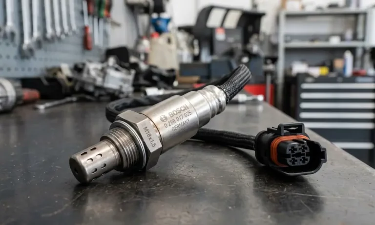
| Bosch / Universal | Black | Grey | White | White |
| Toyota / Lexus | Blue | White | Black | Black |
| Honda / Acura | White | Green | Black | Black |
| Ford | Red | Grey | White | White |
| Nissan / Infiniti | White | Black | Red | Red |
| Delphi | Purple | Tan | Black | Black |
Don’t know what brand sensor you’re dealing with? Test for resistance first. The two wires showing 5–20 ohms are always the heater pair. Of the remaining wires, the one that generates voltage when you heat the tip is the signal wire.
How to Read the Downstream Sensor
The downstream (Sensor 2) sensor works differently from the upstream one. It doesn’t control fuel — it watches the catalytic converter.
A healthy catalytic converter smooths out exhaust fluctuations. So a healthy downstream sensor shows a steady voltage around 0.6–0.8V. That flatline is a good sign.
If the downstream sensor starts switching rapidly like the upstream sensor, the catalytic converter has stopped storing oxygen and is no longer doing its job. That triggers a P0420 code — and the converter usually needs replacement, not the sensor.
| Parameter | Upstream Sensor 1 | Downstream Sensor 2 |
|---|---|---|
| Normal waveform | Fast switching 0.1V–0.9V | Steady 0.6V–0.8V |
| Fault if static? | Yes | No — static is correct |
| Fault if switching? | No — switching is healthy | Yes — means converter failure |
When to Replace vs. Repair
Most O2 sensor problems don’t get repaired — the sensor gets replaced. But before you order a new one, confirm these three things:
- The heater circuit has power and ground — not just a dead fuse
- The wiring harness is intact — no chafed or melted wires
- There are no exhaust leaks upstream — they’ll kill a brand-new sensor’s accuracy instantly
If all three check out and the sensor still fails the voltage or response tests, replace it. Many manufacturers recommend proactive testing around the 100,000-mile mark, even without symptoms. A sensor that’s slightly lazy quietly costs you fuel economy every single day without ever triggering a code.