Is your car hesitating, stalling, or shifting weird? A bad throttle position sensor might be the culprit. This guide walks you through exactly how to test a throttle position sensor using a multimeter, scan tool, and oscilloscope — so you can fix the real problem, not guess at it.
What Does a Throttle Position Sensor Actually Do?
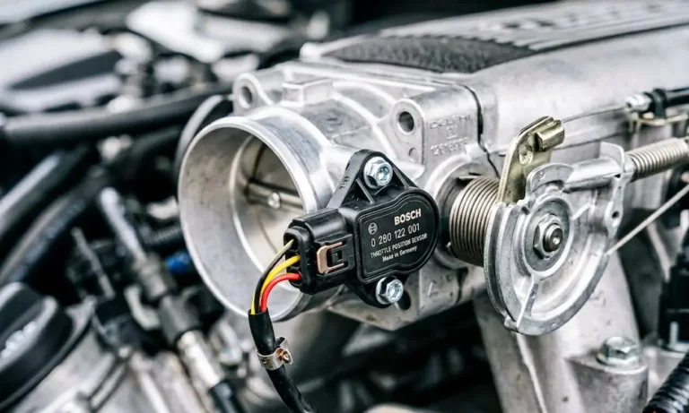
The throttle position sensor (TPS) sits on the throttle body and tracks the angle of the throttle plate. It sends that data to your engine control unit (ECU) as a voltage signal.
Your ECU uses that signal to control:
- Fuel injection timing — how much fuel to spray
- Ignition timing — when to fire the spark plugs
- Transmission shifts — when to upshift or downshift
- Idle control — stopping the engine from stalling at a red light
The signal output follows a simple rule: low voltage at idle (around 0.5V), rising smoothly to around 4.5V at wide-open throttle. Any deviation from that range causes real drivability problems.
Signs Your Throttle Position Sensor Is Failing
A failing TPS rarely dies all at once. It usually nags you first.
Watch for these symptoms:
- Hesitation or stumble during acceleration — the ECU briefly cuts fuel when the signal drops out
- Unstable or hunting idle — RPMs bounce up and down at a stop
- Stalling when you slow down — the sensor tells the ECU the throttle is open when it isn’t
- Harsh or late transmission shifts — the gearbox uses throttle data to decide when to shift
- Check engine light with codes in the P0120–P0124 range
- Limp mode — the car limits speed and power to protect itself
If the engine stumbles only at a specific throttle angle, that’s a classic worn-track fault. The internal wiper hits a dead spot and the signal drops for a split second.
Understanding the Three-Wire Circuit
Before you test anything, you need to know what each wire does. Most TPS connectors have exactly three wires.
| Wire | Function | Expected Voltage |
|---|---|---|
| Reference | ECU sends regulated 5V to power the sensor | 5.0V |
| Ground | Returns directly to the ECU (not chassis ground) | 0.0–0.1V |
| Signal | Reports actual throttle position to ECU | 0.5V (idle) → 4.5V (WOT) |
The ECU uses a clean, dedicated ground — not the body chassis. That keeps electrical noise from the starter and ignition system away from the sensitive voltage signals. A corroded ground wire pushes the signal voltage higher than it should be, tricking the ECU into thinking you’re pressing the gas when you’re not.
How to Test a Throttle Position Sensor with a Multimeter
A digital multimeter is your first and best tool. Run these tests with the ignition on and the engine off — that’s called Key On, Engine Off (KOEO).
Step 1: Visual Inspection First
Don’t skip this. Unplug the connector and look closely at the pins. Check for:
- Bent or corroded terminals
- Cracked or brittle wire insulation
- Oil or moisture inside the connector
- Carbon buildup around the throttle body
Spray any dirty terminals with electrical contact cleaner before testing. A corroded pin adds resistance and skews every reading you take.
Step 2: Test the 5V Reference and Ground
Disconnect the sensor. Set your multimeter to DC voltage.
- Reference wire test: Red lead to the reference pin in the harness, black lead to battery negative. You should see close to exactly 5.0V.
- Ground wire test: Red lead to battery positive, black lead to the ground pin. You should see battery voltage (around 12V). If it reads significantly less, you’ve got a high-resistance ground.
No 5V reference? The ECU isn’t powering the sensor. That’s a wiring or ECU fault — not the sensor itself.
Step 3: The Dynamic Signal Sweep Test
This is the most important test. It checks the sensor across its full range of motion — not just at idle.
Reconnect the sensor. Use back-probing to insert a thin needle probe into the back of the signal wire terminal. Don’t pierce the insulation — slide the probe in from the rear of the connector alongside the wire.
- Set multimeter to DC voltage, black lead to clean engine ground
- Insert red lead probe into the signal wire terminal
- Note the voltage at closed throttle — should be 0.5V to 0.9V
- Slowly open the throttle by hand or have someone press the pedal gently
- Watch the display — voltage should rise smoothly and continuously
- At wide-open throttle, voltage should reach 4.1V to 4.7V
- Slowly release the throttle — voltage should drop just as smoothly
Any sudden jump, freeze, or drop to zero? That’s a dead spot. Replace the sensor.
How to Test a Throttle Position Sensor with a Scan Tool
A scan tool shows you the computed data the ECU actually uses — which is different from the raw voltage.
Reading Live TPS Data
Connect the scan tool and navigate to live data PIDs. Look for these two readings:
- Absolute Throttle Position — raw sensor data, expressed as a percentage. At idle on modern cars, 3–10% is normal, not zero. The throttle stays slightly open to allow idle airflow.
- Relative Throttle Position — the ECU subtracts the idle baseline. This should read 0% at idle and near 100% at full throttle.
If absolute throttle position jumps erratically while relative stays stable, the ECU is filtering the bad signal. That’s a clue the sensor is marginal — not dead yet, but failing.
Graph the Data
Use your scan tool’s graphing function. Plot throttle position while slowly pressing and releasing the pedal. A healthy sensor draws a smooth ramp up and back down. A failing sensor shows vertical spikes or flat plateaus where the signal stuck or dropped out. Graphs make it much easier to catch intermittent faults than watching numbers flicker.
Diagnostic Trouble Codes to Know
| DTC | Definition | Common Cause |
|---|---|---|
| P0120 | TPS Circuit Malfunction | Connector or wiring failure |
| P0121 | TPS Range/Performance | Signal doesn’t match engine load |
| P0122 | TPS Circuit Low Input | Short to ground or open circuit |
| P0123 | TPS Circuit High Input | Short to 5V reference |
| P0124 | TPS Circuit Intermittent | Loose connection or worn track |
A P0121 is tricky — the sensor circuit tests fine electrically, but the signal doesn’t make logical sense compared to what the MAP and MAF sensors report. That’s a rationality fault, and it often points to a sticky throttle plate rather than a bad sensor.
How to Test a Throttle Position Sensor with an Oscilloscope
Some faults last only milliseconds. A multimeter averages its readings and misses them. A scan tool’s refresh rate is too slow. For those elusive stumbles that happen once at 65 mph, you need an oscilloscope.
Setting Up the Scope
Connect the oscilloscope the same way as your multimeter — back-probe the signal wire, ground probe to a clean engine ground.
Use these settings:
- Voltage scale: 1 volt per division
- Time base: 500ms to 1 second per division
- Trigger: Set to normal trigger just above idle voltage
Reading the Waveform
A healthy sweep looks like a straight, diagonal ramp from bottom-left to top-right and back. Any vertical spikes, jagged sections, or sudden drops to zero volts indicate a microscopic fault in the resistive track. Even a dropout lasting one millisecond is enough to cause the ECU to cut fuel and make the car stumble.
Testing Dual Sensors on Drive-By-Wire Systems
Modern cars use Electronic Throttle Control (ETC) — no cable, just an electric motor moving the throttle plate. These systems run two independent TPS sensors in one housing to meet safety requirements.
The ECU constantly compares both signals. If they disagree, the ECU shuts down the throttle motor and limits power immediately. The two sensors typically work in opposite directions — Sensor A rises from 0.5V to 4.5V while Sensor B falls from 4.5V to 0.5V. That mirrored relationship makes it impossible for a single wiring fault to fake a valid reading.
To test dual sensors, use a scan tool that can graph both TPS 1 and TPS 2 simultaneously. If the lines don’t mirror each other cleanly throughout the sweep, replace the entire sensor assembly.
Don’t Confuse TPS Faults with These Other Issues
The TPS doesn’t work alone. Your ECU cross-checks it against the MAP and MAF sensors constantly.
| Scenario | TPS Signal | MAP Signal | MAF Signal | What It Means |
|---|---|---|---|---|
| Normal idle | Low (~0.5V) | High vacuum | Low flow | All good |
| Normal acceleration | Rising smoothly | Vacuum dropping | Flow rising | All good |
| Faulty TPS | Erratic/jumping | Stable | Stable | Sensor or wiring fault |
| Sticky throttle plate | High (fixed) | High pressure | High flow | Mechanical blockage |
| Clogged intake | High (WOT position) | Low pressure | Low flow | Air restriction |
If the TPS signal is smooth but the car still runs badly, check your MAF sensor next. If the throttle commands wide open but vacuum stays high, you’ve likely got a sticky or carbon-clogged throttle plate — not a sensor fault.
Carbon buildup on the throttle butterfly is surprisingly common and often triggers a P0121. Clean the throttle body with a dedicated throttle cleaner before replacing parts.
After Replacing the Sensor — Run the Relearn
Install the new sensor with the throttle shaft tang correctly aligned. Don’t force it. A misaligned install crushes the internal mechanism instantly.
After installation, the ECU needs to learn the new sensor’s idle voltage baseline. Every sensor is slightly different electrically.
- Manual relearn: Turn ignition on, slowly press and release the accelerator pedal three full times, then start the engine.
- Scan tool relearn: Use the TPS relearn or throttle body relearn function in your scan tool. The ECU moves the throttle motor through its full range and stores the new voltage limits to memory.
Skip the relearn and you’ll likely get a high idle, surging, or an immediate check engine light. The ECU applies the old sensor’s offsets to the new one and gets confused.
Knowing how to test a throttle position sensor correctly — from visual inspection through oscilloscope analysis — means you fix the actual problem on the first attempt. No parts-cannon guessing. Just clean diagnostics and a car that drives the way it should.