Your car cranks but won’t start, or it stalls randomly at the worst moments. The crankshaft position sensor might be the culprit. This guide shows you exactly how to check crankshaft position sensor using real diagnostic steps — no guesswork, no wasted parts. Stick around, because the fix might be simpler than you think.
What Does a Crankshaft Position Sensor Actually Do?
Think of it as your engine’s heartbeat monitor. The crankshaft position sensor tracks the exact speed and position of the crankshaft and sends that data to the engine control module (ECM). The ECM uses that data to time fuel injection and spark plug firing.
No signal? The ECM shuts everything down. No fuel, no spark, no start.
The sensor is the primary timing reference for the entire engine management system. That’s a big job for a small part.
Signs You’ve Got a Bad Crankshaft Position Sensor
Before you grab any tools, check if these symptoms match what your car is doing.
Common warning signs include:
- Engine cranks but won’t start
- Random stalling with no warning
- Tachometer drops to zero while driving
- Rough idle or engine vibration
- Hesitation or stumbling during acceleration
- Check engine light turns on
- Worse fuel economy than usual
Intermittent stalling is one of the sneakiest symptoms. The sensor works fine when cold but fails once the engine heats up. That’s because heat causes tiny cracks in the sensor’s internal components to expand and break the circuit.
A failing sensor can push your ECM into open-loop mode, where it uses fixed fuel maps instead of live data. That tanks your fuel economy fast.
Step 1 — Read the Diagnostic Trouble Codes First
Don’t skip this step. Plug an OBD-II scan tool into the diagnostic port under your dashboard. Turn the ignition to the “on” position and pull any stored codes.
Here’s what the common crankshaft sensor codes mean:
| Code | Description | What It Likely Means |
|---|---|---|
| P0335 | Circuit Malfunction | Total signal loss — dead sensor or broken wire |
| P0336 | Range/Performance Problem | Signal present but erratic or wrong pattern |
| P0337 | Low Input Signal | Voltage too weak for the ECM to read |
| P0338 | High Input Signal | Voltage too high — possible short to power |
| P0339 | Intermittent Circuit | Signal drops in and out — heat or vibration issue |
Haynes Manuals explains that a code doesn’t always mean the sensor itself is dead. The wiring harness or the reluctor wheel could be the real problem. That’s why you need to keep testing beyond the code.
Check live data too. Switch your scan tool to live data mode and watch the engine RPM reading while someone cranks the engine. If the starter is spinning the engine but the scan tool shows zero RPM, the crankshaft sensor circuit has a problem. This is one of the most reliable quick checks you can do.
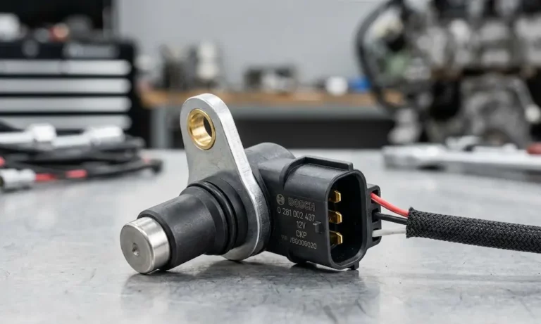
Step 2 — Know Which Type of Sensor You Have
This matters because the two sensor types need different tests. Check your vehicle’s service manual or a parts lookup site to confirm which one you’re dealing with.
| Attribute | Inductive Sensor | Hall Effect Sensor |
|---|---|---|
| Wire Count | Two wires | Three wires |
| Signal Type | Analog sine wave | Digital square wave |
| Power Source | Self-generating | Needs external 5V or 12V |
| What to Measure | Resistance + AC volts | Reference voltage + DC signal |
| Speed Sensitivity | Signal weakens at low RPM | Consistent at any speed |
Hall effect sensors are more common on newer vehicles and are better for modern start-stop systems because they produce a clean digital signal at any speed.
Step 3 — Test an Inductive (Two-Wire) Sensor with a Multimeter
Grab your digital multimeter. Here’s the process:
Resistance Test:
- Disconnect the sensor from the wiring harness.
- Set the multimeter to ohms (Ω).
- Touch the probes to the two sensor pins.
- A healthy sensor reads between 200 and 1,000 ohms, depending on the manufacturer.
What the readings mean:
- Zero ohms — internal short circuit, replace the sensor
- Infinite resistance (OL) — open circuit, the internal coil is broken
- Within range — resistance is fine, keep testing
Do this test twice — once when the engine is cold and again after a warm-up. Some sensors only fail when hot, so a cold resistance test can give you a false pass.
AC Voltage Signal Test:
- Reconnect the sensor.
- Set the multimeter to AC volts (low range, around 2V).
- Back-probe the signal wires at the connector.
- Have someone crank the engine.
- A working sensor produces a fluctuating AC voltage.
You can also do a quick bench test. CarParts.com suggests passing a metal object like a screwdriver rapidly across the sensor tip while watching the multimeter. A working inductive sensor shows a small voltage spike. Nothing? The sensor’s dead.
Step 4 — Test a Hall Effect (Three-Wire) Sensor
This sensor needs power to produce a signal, so the testing approach is different.
Check the reference voltage:
- Turn the ignition to “on” (engine off).
- Set the multimeter to DC volts.
- Probe the power wire at the connector.
- You should see a steady 5V or 12V reference from the ECM.
No voltage? The problem is in the wiring or the ECM output, not the sensor itself.
Check the ground:
- Keep the multimeter on DC volts.
- Touch one probe to the ground wire and the other to the negative battery terminal.
- You want near-zero resistance. Any significant voltage drop signals a bad ground connection.
Check the signal output:
- Leave the sensor connected.
- Back-probe the signal wire at the back of the connector using a thin pin.
- Set the multimeter to DC volts.
- Crank the engine or rotate it by hand.
- The signal wire should toggle rapidly between zero and the reference voltage.
If the voltage stays stuck at either high or low while the crankshaft is moving, the sensor’s internal switching circuit has failed. Replace it.
Step 5 — Inspect the Sensor and Reluctor Wheel Physically
Electrical tests only tell part of the story. A physical check can reveal problems that no multimeter will catch.
Look for these issues:
- Metal debris on the sensor tip — The sensor’s magnetic field attracts tiny iron particles from engine wear. This buildup distorts the signal. This is a common but overlooked failure cause.
- Oil contamination — Many sensors sit near oil seals. Oil can wick through the wiring harness and cause shorts or high resistance far from the sensor itself.
- Frayed or cracked wiring — Check the harness from the sensor back toward the ECM for any damage from heat or rubbing.
- Chipped or bent reluctor wheel teeth — A damaged tone ring produces a corrupted signal. Ersa Electronics notes that on engines where the reluctor wheel is part of the harmonic balancer, a failed rubber damper can make the wheel wobble and cause timing errors that are hard to diagnose without a visual look.
- Scrape marks on the sensor tip — This tells you the air gap was too small or that crankshaft bearing wear caused the crankshaft to shift position.
The air gap — the distance between the sensor tip and the reluctor wheel teeth — must fall within the manufacturer’s spec. A gap that’s too large weakens the magnetic signal, especially at low speeds. Most modern sensors aren’t adjustable, but you can visually check that the mounting position looks right and that nothing is bent or shifted.
Step 6 — Check for Camshaft and Crankshaft Correlation
Here’s something most people miss. The ECM constantly compares the crankshaft signal against the camshaft position sensor signal. If they don’t line up, it may not be a sensor problem at all.
A stretched timing chain or skipped timing belt produces the exact same codes as a bad crankshaft sensor. Replacing the sensor won’t fix a mechanical timing fault.
If both sensors test fine electrically but the correlation codes keep coming back, inspect the timing chain or belt before ordering any more parts.
Step 7 — Run the Relearn Procedure After Replacement
You replaced the sensor. Don’t just start the engine and drive away. Many vehicles need a relearn procedure before the ECM accepts the new sensor’s signal correctly.
Skipping this step can leave you with subtle performance problems or a “Crankshaft Variation Not Learned” trouble code even with a brand-new sensor installed.
The four relearn methods are:
- Battery reset — Disconnect the battery for a set time to clear adaptive memory
- Idle calibration — Let the engine idle for a specific period after the first start
- Drive cycle — Drive at specific speeds and loads so the ECM can map the new signal
- Scan tool command — Use a professional scan tool to trigger the relearn while the engine runs
Check your vehicle’s service manual or a model-specific forum for the exact procedure. Some vehicles do it automatically. Others need a scan tool with bidirectional control to run it manually.
Don’t Overlook the Wiring Harness
If your sensor tests fine but codes keep coming back, the harness deserves serious attention. Many crankshaft sensor harnesses use shielded cable to block interference from the alternator and ignition coils. When you repair damaged wires, you must maintain that shielding. Use weather-tight connectors and keep the repair away from heat sources. A poor splice in this circuit creates exactly the kind of noisy, intermittent signal that drives even experienced mechanics up the wall.
Quick Diagnostic Summary
| Tool | What It Checks | What You’re Looking For |
|---|---|---|
| OBD-II Scan Tool | Stored codes + live RPM data | P0335–P0339, zero RPM during crank |
| Digital Multimeter | Resistance + voltage | 200–1,000Ω, reference voltage, signal toggling |
| Visual Inspection | Physical condition | Debris, oil, cracked wires, damaged reluctor |
| Oscilloscope | Signal waveform quality | Clean sine or square wave with no dropout |
Knowing how to check crankshaft position sensor the right way saves you from throwing money at parts that aren’t the problem. Start with the codes, test the sensor electrically for your sensor type, inspect the physical components, and always run the relearn after a replacement. Follow these steps in order and you’ll find the real fault every time.