
Ball joint replacement sounds straightforward until your press slips, your control arm cracks, or the joint won’t budge. This guide walks you through exactly how to use a ball joint press the right way — from tool setup to final installation. Stick around, because the details here can save you hundreds in damaged parts.
What a Ball Joint Press Actually Does
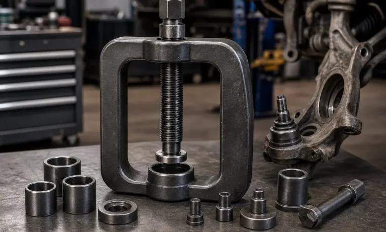
A ball joint press is a heavy-duty C-frame tool that uses a threaded jackscrew to push press-fit ball joints in and out of control arms and axle yokes. Think of it as a massively reinforced C-clamp designed to generate tons of controlled linear force.
You can’t do this job with a hammer alone. Ball joints sit in a tight interference fit — meaning the housing is slightly larger than the bore it sits in. That’s intentional. It’s what keeps the joint locked in place. Breaking that fit requires serious, precise force.
Standard ball joint press kits typically include the C-frame body, a forcing screw, several receiving tubes, removal adapters, and installation cups. Professional master kits from brands like Snap-on, OTC, and Orion Motor Tech contain 14 to 23 pieces to cover most domestic and imported vehicles.
Know Your Suspension Before You Start
The type of suspension on your vehicle dictates which adapters you need, how much force the job requires, and what you can accidentally damage.
Independent Front Suspension
Independent front suspension (IFS) lets each wheel move on its own. It’s the dominant design on passenger cars, crossovers, and light trucks because it handles better and rides smoother.
The catch? Many modern IFS control arms use aluminum or thin stamped steel to cut weight. Aluminum is soft. Misalign the press even slightly, and you’ll gouge, gall, or stretch the bore — which destroys the interference fit and turns a $30 ball joint job into a $300+ control arm replacement.
4WD and AWD vehicles add another problem: the CV axle shaft runs right through your workspace, limiting clearance and often requiring extra disassembly before the C-frame even fits.
Solid Axle Suspension
Solid axles connect both wheel hubs through one rigid housing. You’ll find them on heavy-duty trucks like the Ford Super Duty (F-250 through F-550), Dodge Ram 2500/3500, and Jeep platforms. These commonly use Dana 30, 44, 50, or 60 axle variants.
On solid axles, ball joints press directly into the forged axle yokes (called the “inner C”). The problem here is geometry: those cast yoke surfaces aren’t flat. Running a flat-faced press against an angled casting will cause the tool to kick sideways violently under load. You need specialized slanted adapters that mate flush with the Dana yoke surface.
| Suspension Type | Common Vehicles | Key Challenges |
|---|---|---|
| Independent Front Suspension | Cars, crossovers, light trucks | Soft aluminum bores, tight CV axle clearance |
| Solid Axle (Dana 44/60) | Ford Super Duty, Dodge Ram, Jeep | Extreme force needed, angled yokes require slanted adapters |
Safety First — This Step Isn’t Optional
Working under a lifted vehicle is one of the most dangerous things you can do in a garage. A floor jack can fail without warning. Don’t work under a car supported only by one.
Lift It Right
Park on level, solid concrete — not asphalt. Asphalt softens in warm weather, and jack stand feet sink into it, destabilizing the whole vehicle. Use wheel chocks on both sides of the tires on the opposite axle.
Once the vehicle is at working height, lower it onto quality mechanical jack stands at the manufacturer’s designated lift points. In the U.S., professional jack stands must meet ASME PASE or ANSI/ASME PALD standards — these are tested to hold 200% of their rated capacity.
One important detail: jack stand tonnage ratings apply to the matched pair, not each individual stand. When working on a heavy diesel truck with 4,000+ lbs over the front axle, use 6-ton stands — not the standard 3-ton set.
After the vehicle is on the stands, shake the chassis firmly. If anything shifts or creaks, reposition before you start wrenching.
Gear Up
Wear ANSI-approved safety glasses or a full face shield. Metal fragments, rust scale, and pressurized grease don’t care about your eyeballs. Heavy gloves and steel-toed boots round out the basics. Remove jewelry, lanyards, and loose clothing — the forcing screw rotates under load.
Disassembling the Suspension for Access
With the wheel off, you need to clear the ball joints before the press goes anywhere near them.
Remove the brake caliper first. Never let it hang by the rubber brake hose — the weight will rupture the internal lining and kill your brake pressure. Wire it up to a spring or the chassis.
Pull the rotor, caliper bracket, and if applicable, unbolt the wheel hub. On 4WD/AWD/FWD vehicles, remove the CV axle nut and gently push the shaft back through the hub. Don’t overextend the inner CV joint — pulling the tripod bearings out of the housing turns a suspension job into a driveline job.
Next, disconnect the outer tie rod end and remove the ball joint stud nuts. If they use castle nuts and cotter pins, cut and discard the pins — cotter pins are single-use only.
To separate the tapered ball joint stud from the steering knuckle, you have two options:
- Mechanical separator tool: A screw-type press tool that quietly pushes the stud free without damage. Best option if you’re reusing the joint.
- Pickle fork: Hammered between the knuckle and arm. Fast and effective, but it shreds the dust boot every time. Fine if the joint is being replaced anyway.
How to Remove a Ball Joint With the Press
With the knuckle off, you’ve got clear access. Here’s how to use a ball joint press step by step for removal.
Clean the Area First
Wire brush all the rust and packed dirt away from around the ball joint housing and control arm bore. Spray penetrating fluid generously around the entire joint perimeter. This isn’t optional — packed debris prevents the receiving tube from seating flat, which causes misalignment that can destroy the press and the control arm.
Check for a snap ring or retaining clip first. If one is present, remove it with snap ring pliers before applying any pressing force. Pressing against a locked snap ring will crack the control arm.
Set Up the Press
Lubricate the forcing screw threads. This step matters more than people realize. Running a dry jackscrew under heavy load will gall the threads and destroy the tool. Use anti-seize compound or extreme-pressure molybdenum grease every single time.
Then follow this sequence:
- Choose your receiving tube. The inner diameter must fully clear the ball joint body. The outer diameter must rest solidly on the control arm metal — not overlapping the bore.
- Place the removal adapter on the ball joint stud to give the forcing screw a flat, centered surface to push against.
- Position the C-frame over the assembly with the jackscrew on the stud side and the receiving tube captured on the opposite side.
- Check alignment from multiple angles. The forcing screw, ball joint, bore, and receiving tube all need to share a perfectly straight center axis. A slight angle means the joint binds, the control arm gets damaged, and adapters can rocket out under tension.
Apply steady torque with a breaker bar or high-torque impact. You’ll often hear a loud pop as the rust bond breaks — that’s the joint releasing. After that, it presses out with moderate resistance.
When It Won’t Budge
Severely corroded joints — common in Rust Belt states and coastal regions — sometimes refuse to move even under maximum jackscrew torque. Don’t just crank harder. That risks bending the C-frame or stripping the threads.
The trick: with the press under heavy static tension, strike the control arm next to (not on) the ball joint bore with a heavy sledgehammer. The shockwave distorts the bore microscopically for a split second, breaking the rust bond. The tensioned jackscrew does the rest. This technique works extremely well and saves your tool from destruction.
How to Install a Ball Joint With the Press
Clean the bore thoroughly with fine emery cloth before installing the new joint. Even a micro-layer of rust causes the joint to bind prematurely — which makes it feel fully seated when it isn’t. Lightly coat the clean bore with anti-seize compound.
The Thermal Trick That Actually Works
Freezing the new ball joint overnight before installation works. Cold metal contracts. A frozen ball joint has a slightly smaller diameter, making it easier to start in the bore. If you simultaneously heat the control arm bore gently with a heat gun, the two metals work together to reduce press resistance dramatically.
The catch: thermal transfer between metals happens fast. The moment the frozen joint touches the warm bore, you have seconds before the interference fit re-establishes. Have the press fully assembled and ready to go the moment the joint comes out of the freezer.
Installing the Joint
The C-frame flips direction for installation — you’re pressing the joint in, not out.
- Hand-start the joint square in the bore. If it goes in crooked, stop immediately. A cocked joint will gouge the bore and bind permanently.
- Select the installation cup carefully. It must contact only the outer steel flange of the ball joint housing. If it touches the center stud, the dust boot, or the internal bearing cover, the jackscrew will crush the internals and ruin the new part before the car moves an inch. This creates a dangerous “memory steer” condition where the wheel won’t return to center after turning.
- Place the receiving tube on the exit side — deep enough to allow the stud to protrude freely as the housing seats fully.
- Press slowly and evenly. If you feel sudden sharp resistance immediately, the joint is cocking. Release tension, tap it square with a brass mallet, and restart.
Press until the flange sits completely flush against the control arm. Check the full circumference — no gaps anywhere. Install the snap ring to lock it in position.
Special Ball Joints That Need Extra Attention
Not every replacement ball joint installs the same way.
Knurled ball joints solve a specific problem: worn or stretched control arm bores that won’t grip a standard smooth joint. Brands like Moog Problem Solver engineer knurled housings with raised steel ridges that cut into the bore during installation, restoring the interference fit. For severely worn bores, you can use a center punch to raise small craters inside the bore before pressing — this gives the knurls more material to bite into.
Elliptical opening ball joints use an oval stud hole instead of a round one. Installing one out of rotational phase means normal suspension travel forces the stud into the housing edge, fracturing the joint. Always match the alignment marks to the correct axis before pressing.
Pinch-bolt style ball joints use a straight stud with a groove for a cross-bolt. The knuckle height on the stud must be exact. Too high or too low, and the bolt won’t align with the groove — forcing it through will strip the knuckle threads.
Greaseable (Zerk fitting) ball joints need their fitting oriented toward open space before you press them in. Once pressed, the housing doesn’t rotate. A fitting buried behind an axle shaft or dust shield means you’ll never be able to grease the joint at service intervals. Aim it toward a clear angle — rear-facing works on most setups. Use 45° or 90° angled Zerk fittings if clearance is still tight.
The Ball Joint Press Works for U-Joints Too
The same C-frame handles universal joint replacement on driveshafts and solid front axle half-shafts. The process is nearly identical — remove the retaining clips, press each bearing cap out into a receiving tube, reverse the press to install the new caps.
One tip from experienced techs: freeze the new bearing caps before installation. Cold grease thickens and holds the needle bearings against the cup walls. If a needle falls over during pressing, it crushes flat and ruins the U-joint before it ever turns.
Heavy-duty commercial trucks also use the C-frame for brake anchor pin extraction — those thick steel pins that press into brake spiders and corrode completely solid over time. The press removes them cleanly without hammer damage to the surrounding hardware.
The Difference Between a Good Install and a Comeback
Learning how to use a ball joint press correctly comes down to three non-negotiable habits: lubricate the forcing screw every single time, verify concentric alignment before applying heavy torque, and use the right installation cup to protect the new joint’s internals.
Skip any one of these, and you’re either ruining expensive parts or sending a vehicle back onto the road with a suspension component that’ll fail when it matters most. The tool is straightforward — the discipline is what separates a clean repair from a dangerous one.


