
Your speedometer is dead, your ABS light is on, or your transmission is shifting like it’s angry at you. Sound familiar? A faulty speed sensor is usually the culprit. This guide shows you exactly how to test a speedometer sensor at home — no guesswork, no unnecessary parts replaced.
What Does a Speedometer Sensor Actually Do?
The speed sensor isn’t just feeding your speedometer needle. It’s the backbone of several critical systems running simultaneously.
Your engine control module uses it for fuel delivery during deceleration. Your transmission control module uses it to decide when to shift gears. Your ABS module uses it to detect wheel lockup. Lose that signal, and multiple systems go haywire at once.
That’s why testing the speedometer sensor properly matters — not just slapping in a new one and hoping for the best.
Know Your Sensor Before You Test It
You need to identify which type of speed sensor your vehicle uses. Testing methods differ significantly between the two main types.
Variable Reluctance (Passive) Sensors
These sensors have two wires and no external power source. They generate their own AC voltage signal through electromagnetic induction. A rotating toothed gear passes the sensor tip, which causes the magnetic field to fluctuate and creates a sine wave signal.
The catch? Their signal gets weaker at very low speeds. That’s a known limitation — not a fault.
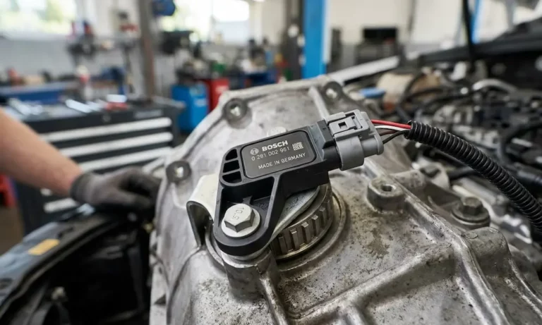
Hall Effect (Active) Sensors
These sensors have three wires: power, ground, and signal. They need 5V or 12V from the vehicle to operate. Instead of a sine wave, they output a clean digital square wave that toggles between high and low voltage as gear teeth pass by.
They read accurately even at near-zero speed, which is why modern ABS and stability control systems depend on them.
| Feature | Variable Reluctance | Hall Effect |
|---|---|---|
| Wires | 2 | 3 |
| Power Needed | No | Yes (5V–12V) |
| Signal Type | AC Sine Wave | DC Square Wave |
| Low-Speed Accuracy | Poor | Excellent |
| Typical Use | Older ABS, transmission output | Modern ABS, wheel hubs |
Warning Signs Your Speed Sensor Is Failing
Before grabbing your multimeter, check whether these symptoms match your situation. A bad speedometer sensor often shows up as several problems at once.
- Erratic or dead speedometer needle — the most obvious sign
- Transmission slamming into gear or getting stuck in limp mode (locked in 2nd or 3rd gear)
- ABS or traction control warning lights illuminated on the dash
- Cruise control that won’t engage — the computer disables it as a safety measure
- Engine stalling at traffic lights — the ECM doesn’t know you’ve slowed down
- Odometer stops counting — it runs off the same signal
- Poor fuel economy — the torque converter clutch won’t lock without speed confirmation
Metallic debris accumulating on the sensor tip is one of the most common causes of weak or intermittent signals — and it’s completely fixable without replacing the sensor.
Tools You’ll Need
Don’t skip this step. Using the wrong meter or the wrong method can give you false readings — or damage the control module.
- Digital multimeter — use a high-impedance model to avoid drawing excess current from the circuit
- Back-probing pins — thin needles that slide past connector seals so you can test live circuits without unplugging anything
- OBD-II scan tool — reads fault codes and shows live sensor data in real time
- Oscilloscope (optional but useful) — lets you see the actual waveform shape, which catches problems a multimeter misses
- Breakout leads — jumper wires for safely connecting your meter in parallel with the sensor circuit
Back-probing pins versus breakout leads serve different purposes — back-probes work best for live voltage readings, while breakout leads suit in-series current measurements.
Safety First: Don’t Skip This
Working near spinning wheels or under a raised vehicle isn’t casual work.
- Park on flat, level concrete — no slopes
- Engage the parking brake and chock the wheels that stay on the ground
- Use jack stands rated for your vehicle’s weight — never rely on a floor jack alone
- Disconnect the negative battery terminal for resistance tests (reconnect it for voltage and signal tests)
- Wear safety goggles — brake dust and rust fall straight into your eyes when you’re looking up
These aren’t optional. Safe workshop practice is what separates a productive afternoon from a trip to urgent care.
How to Test a Variable Reluctance (Passive) Sensor
Step 1 — Resistance Test (Static)
- Unplug the sensor from the vehicle harness completely
- Set your multimeter to the Ohms (Ω) setting
- Touch the meter probes to both sensor pins
- A healthy sensor reads between 450 and 2,200 ohms
- “OL” (open loop) means the internal coil is broken — replace the sensor
- A reading below 100 ohms means the coil is shorted — replace the sensor
Now test for an internal ground short. Touch one probe to a sensor pin and the other to the metal sensor body. You should see infinite resistance. Any continuity here means the sensor has an internal short to ground and needs replacing.
Step 2 — Dynamic AC Voltage Test (Live)
This test confirms the sensor actually generates a signal when the wheel turns.
- Reconnect the sensor and use back-probing pins to access both terminals
- Set your multimeter to AC Voltage (millivolt range if available)
- Spin the wheel at roughly one full rotation per second
- A working sensor produces 50mV to 700mV AC
- Spin faster — the voltage should climb steadily
If the voltage stays flat or drops to zero at higher speeds, the sensor magnet may be weak or the tone ring is damaged.
| VR Sensor Test | Healthy Reading | Fault Indication |
|---|---|---|
| Static Resistance | 450–2,200 Ω | OL (open) or under 100 Ω |
| Pin to Sensor Body | Infinite (OL) | Any continuity |
| Low Speed AC Output | 50mV–700mV | 0V or barely fluctuates |
| High Speed AC Output | Voltage increases | Stays flat or cuts out |
How to Test a Hall Effect (Active) Sensor
Step 1 — Check Reference Power and Ground
- Unplug the sensor
- Turn the ignition to “ON” — engine off
- Set your multimeter to DC Volts
- Probe between the power pin (VCC) and ground pin on the vehicle-side connector
- You should see either 5V or 12V depending on your vehicle
- No voltage? Check fuses first, then trace the power wire for breaks
Switch to resistance mode and check ground continuity between the ground pin and the vehicle chassis. It should read less than 0.5 ohms. Higher than that means you’ve got a corroded ground connection — clean it before blaming the sensor.
Step 2 — Signal Pulse Test (Live)
- Plug the sensor back in
- Use a back-probe pin to tap the signal wire without disconnecting anything
- Set your multimeter to DC Volts (or Hz if your meter has it)
- Slowly rotate the wheel by hand
- The voltage should toggle between near 0V and near the reference voltage as gear teeth pass
If the voltage stays locked at one value while the wheel spins, the sensor’s internal transistor has failed — it can no longer switch states. Replace the sensor.
Using the Hz frequency setting is even cleaner. Spin the wheel faster and watch the frequency number climb. It should rise in direct proportion to wheel speed.
3-Wire Hall Sensor Wire Guide
| Wire Color (Common) | Function | Expected Reading |
|---|---|---|
| Red or Orange | Power (VCC) | 5V or 12V constant |
| Black or Brown | Ground (GND) | 0V / continuity to chassis |
| Blue, Green, or White | Signal (SIG) | Toggles 0V to reference voltage |
The Tricky One: 2-Wire Active Sensors
Some late-model vehicles — especially European brands — use a 2-wire active sensor that looks like a passive sensor but behaves like a Hall effect sensor. A standard resistance test won’t give you meaningful results on these.
These sensors work on a current-loop system. The control module sends a bias voltage down the signal wire, and the sensor changes its internal resistance to draw either 7mA or 14mA depending on whether a gear tooth is present or not.
How to test it:
- Back-probe both wires with the sensor plugged in and the ignition ON
- You should see a bias voltage of 1.5V to 12V at rest
- Spin the wheel — a working sensor creates a small square wave ripple riding on top of that steady voltage
If you don’t have an oscilloscope to see the ripple, swapping the suspect sensor with the one from the opposite wheel (if applicable) and checking whether the fault code follows it is a legitimate diagnostic shortcut.
Using an OBD-II Scanner to Speed Up the Diagnosis
Manual electrical tests are reliable, but your scan tool can cut diagnostic time significantly when you know what to look for.
Live Data Monitoring
Connect your scanner and navigate to the speed-related PIDs:
- VSS (Vehicle Speed Sensor) — the general speed signal from the transmission
- LF / RF / LR / RR Wheel Speed — individual wheel speeds in the ABS module
Drive in a straight line at a steady 20 mph. All four wheel speeds should match closely. If one wheel reads 0 mph or jumps erratically while the others are steady, you’ve found your faulty circuit without touching a multimeter.
Reading Freeze Frame Data
When the computer sets a speed sensor fault code, it freezes a snapshot of vehicle conditions at that exact moment. This data tells you more than just “something failed.”
- A fault that only appears at 65 mph? Suggests a vibration issue or a cracked tone ring
- A fault appearing at 2 mph? Points to a wide air gap or magnetic debris damping the signal at low speeds
- Check the transmission temperature in the freeze frame — some sensors only fail once the fluid reaches operating temperature, as heat causes wire windings inside the sensor to expand and break contact
Mechanical Problems That Mimic Sensor Failures
Not every speed sensor fault code means the sensor itself is bad. Mechanical conditions in the sensor’s environment can create identical symptoms.
Air Gap Issues
The sensor tip needs to sit within 0.015 to 0.050 inches of the rotating tone ring. A worn wheel bearing lets the hub wobble, causing the gap to fluctuate with every rotation. You’ll get an intermittent signal that produces codes without the sensor being defective at all.
Rust buildup on the mounting surface — sometimes called “rust jacking” — can physically push the sensor away from its mounting hole and widen the gap beyond the usable range.
Tone Ring Damage
The tone ring is the toothed target your sensor reads. In climates with road salt, water works between the axle and the ring, and the resulting rust expansion can crack the ring entirely. A cracked ring creates an enlarged gap between two teeth. Every time that gap passes the sensor, the computer sees it as a wheel suddenly locking up — and your ABS activates during completely normal stops.
Wiring Harness Fatigue
Speed sensor wires run along suspension arms that flex thousands of times per mile. The copper strands inside can break while the outer insulation looks perfectly fine. This creates an intermittent fault that only appears when the suspension compresses or the wheels turn to a certain angle — the kind of problem that drives people crazy because it won’t reproduce in the driveway.
Check connectors near the wheel hubs for green corrosion on the pins. That corrosion acts as a resistor, weakening the signal and causing low-speed dropouts even when the sensor itself is still functional.
The Smart Diagnostic Order
Work through these steps in sequence. Start with the least invasive and build up from there.
- Scan all modules — ECM, TCM, and ABS — for related fault codes and document every symptom
- Visual inspection — look at the sensor tip, tone ring, and wiring harness for obvious damage or debris
- Live data road test — monitor wheel speeds on the scanner while driving and watch for dropouts
- Connector inspection — unplug the sensor and check for moisture, pushed-out pins, or corrosion
- Manual electrical testing — run the resistance, voltage, and signal pulse tests described above
- Mechanical check — measure the air gap and check for bearing play or tone ring damage
- Clear codes and road test — confirm the repair actually solved the problem before calling it done
Following this order means you’re targeting the root cause rather than replacing parts randomly until the problem goes away by accident.