Struggling with a flooding Edelbrock, a rough idle, or a bog on acceleration? A proper Edelbrock carburetor rebuild fixes all of that. This guide walks you through every step — from teardown to final tuning — so you can get your carb running right the first time. Stick around to the end; the tuning section alone is worth it.
What Makes Edelbrock Carbs Different
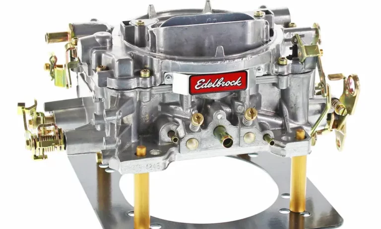
Before you pull a single screw, it helps to know what you’re working with.
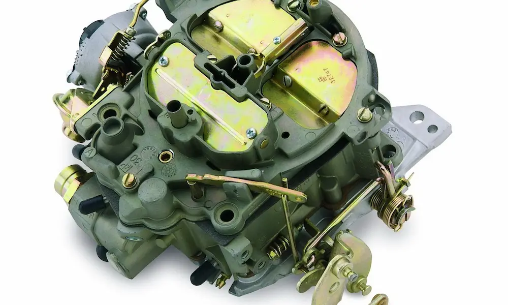
The Edelbrock square-bore design uses a two-piece all-aluminum construction — a main body and a removable airhorn (the “lid”). Unlike carbs with gaskets sitting below the fuel line, Edelbrock’s layout keeps gaskets above the fuel level. That means fewer external leaks and less weeping over time.
The aluminum body also sheds heat faster than zinc alloy units, which cuts down on fuel percolation when the engine bay gets hot.
Here’s a quick breakdown of the model lineup:
| Model Category | Booster Design | Secondary Control | CFM Range | Best For |
|---|---|---|---|---|
| Performer Series (1405, 1406) | Down-leg | Fixed counterweight | 500–750 | Street / mild builds |
| AVS Series | Down-leg | Adjustable spring | 650–800 | Performance street |
| AVS2 Series | Annular flow (8-hole) | Adjustable spring | 500–800 | High-response / modern street |
| VRS-4150 | High-performance annular | Race calibrated | 650–950 | Competition / track |
The AVS2’s annular boosters spray fuel through eight evenly spaced orifices instead of one. That creates a uniform fuel cone, stronger signal strength, and a much smoother transition from idle to main circuit — no stumble.
Before You Rebuild: Check These First
Here’s the truth: most carburetor problems aren’t the carb’s fault. Before you rebuild anything, rule out these issues.
Fuel Pressure
Edelbrock needle and seat assemblies are pressure-sensitive. Too much fuel pressure pushes the needle off its seat and floods the engine.
- Optimal range: 4.5 – 5.5 psi
- Maximum: 6.5 psi
If your pump runs higher, install a regulator before you do anything else. Also fit a 40-micron inline fuel filter between the pump and carb inlet. One tiny rust flake in the needle and seat will cause flooding — guaranteed.
Vacuum Leaks
A vacuum leak fakes a lean condition and destroys idle quality. Check the carb-to-manifold surface — it must be clean and flat. Never use RTV or gasket cement on the base gasket. That stuff extrudes into the throttle bores and vacuum passages, and it creates more problems than it solves.
Know your vacuum ports too:
- Manifold vacuum port – constant vacuum, used for transmission modulators
- Timed (ported) vacuum port – opens after the throttle blades move, used for distributor advance
- PCV port – 3/8″ port, front center
- Power brake port – 1/4″ NPT, rear of carb
Disassembly: Step-by-Step Teardown
Work on a clean, flat bench. Use small containers to keep jets, check balls, and springs organized. Losing a check ball means starting over.
Safety First
- Let the engine cool completely
- Disconnect the negative battery terminal
- Mark all throttle, kickdown, and cruise control linkages before you pull them
- Use two wrenches on the fuel line fitting — one to hold the carb fitting, one to turn the line nut
- Stuff a clean rag in the intake manifold opening the moment the carb comes off
Upper Component Removal
Start at the top:
- Remove the two step-up piston cover plates and pull the step-up pistons, springs, and metering rods
- Disconnect the choke connector rod, pump connector rod, and choke cam connector rod
- Pull the eight or nine airhorn screws and lift the airhorn straight up — don’t angle it or you’ll snag the accelerator pump
- Invert the airhorn on the bench and slide out the float hinge pins
- Remove the floats and unscrew the needle and seat assemblies with a wide-blade screwdriver
Internal Circuit Disassembly
Inside the main body (fuel bowl):
- Remove the primary and secondary jets with a flat-head screwdriver — keep them separate, they’re often different sizes
- Extract the accelerator pump plunger, return spring, discharge check ball, and check weight
- If the check ball is stuck from varnish, soak it briefly in carb cleaner and use a magnet to pull it out
Cleaning: Don’t Skip This Step
This is where most rebuilds succeed or fail. Aluminum is porous — varnish hides in places you can’t see.
Chemical Cleaning
Berryman Chem-Dip works well on stubborn carbon deposits. It contains cresylic acid, which cuts through hardened varnish fast. The catch? It’s aggressive on aluminum. Keep soak time under four hours or you’ll etch the casting. Rinse thoroughly with water, then blow every passage dry with compressed air immediately.
For lighter cleaning and final rinse work, lacquer thinner or denatured alcohol handles modern ethanol-based fuel residues that petroleum solvents miss.
Ultrasonic Cleaning
This is the gold standard. Ultrasonic cleaners use high-frequency sound waves to create cavitation — tiny imploding bubbles that scrub internal passages you can’t reach with a brush.
- Solution: Simple Green Extreme Aircraft & Precision Cleaner mixed with water. Avoid high-pH household detergents — they pit aluminum.
- Temperature: 50°C – 60°C
- Time: 20 – 30 minutes
- After: Blow every passage with 60–80 psi compressed air. No moisture left behind.
Component Inspection: What to Look For
Once everything’s clean, inspect before you reassemble.
Needle and seat: The Viton-tipped needle in the Edelbrock #1477 rebuild kit should be soft and pliable. If it’s hard, swollen, or has a ring groove worn into the tip from the seat, replace it. E10 fuel swells certain rubber formulations — that sticking needle causes flooding.
Floats: Shake each float near your ear. Hear liquid sloshing? It’s fuel-soaked and it needs replacing. You can also submerge floats in a non-flammable liquid and look for rising bubbles. A heavy, fuel-soaked float sits low and never fully closes the needle valve.
Throttle shaft: Push and pull the primary throttle shaft laterally. Significant play means air leaks past the shaft at idle — that causes a lean, unstable idle you can’t tune out. Fix it with bronze re-bushing sleeves before reassembly.
Reassembly and Float Setting
Use the Edelbrock #1477 rebuild kit. Install all gaskets dry — zero sealant.
Float Height and Drop
The fuel level in the bowls affects every single circuit. Get this wrong and no amount of jet or rod swapping will fix your tune.
| Spec | Performer Series | AVS / AVS2 Series |
|---|---|---|
| Float height | 7/16″ | 7/16″ |
| Float drop | 15/16″ to 1″ | 1-1/4″ to 1-1/2″ |
| Max fuel pressure | 6.5 psi | 6.0 psi |
Setting float height: Invert the airhorn with the gasket in place. Measure from the gasket surface to the outer tip of the float. It should be exactly 7/16″. A 7/16″ drill bit works perfectly as a gauge. Adjust by gently bending the metal tab that contacts the needle.
Setting float drop: Hold the airhorn upright and let the float hang freely. Measure from the gasket to the outer tip — it should fall between 1.25″ and 1.5″ for AVS/AVS2 models.
Step-Up Pistons and Cover Plates
Make sure each step-up piston moves freely in its bore. The metering rods must seat correctly in the primary jets. When installing the cover plate screws, torque them to 12–17 inch-pounds. Over-tighten these and you’ll snap the heads off — those tiny screws can drop straight into your intake manifold. If you don’t have a torque wrench, snug the screw until it contacts the plate, then turn it exactly 1/16 of a turn more.
Tuning: Jets, Metering Rods, and Step-Up Springs
This is where you dial in the air-fuel ratio for your specific engine.
The Edelbrock metering system uses a two-diameter metering rod inside the jet. The thick “cruise diameter” sits in the jet during light throttle. Under heavy load, manifold vacuum drops, the step-up piston lifts, and the thinner “power tip” moves into the jet — richening the mixture. Swapping rods or jets changes the mixture in roughly 4%, 8%, or 12% increments.
Step-up springs control when the power enrichment happens. Here’s the color chart:
| Spring Color | Rating (in. Hg) | Use Case |
|---|---|---|
| Blue | 3″ | Aggressive cams, low idle vacuum |
| Yellow | 4″ | Modified engines |
| Orange | 5″ | Moderate performance |
| Pink | 7″ | Stock / mild builds |
| Silver (Plain) | 8″ | Heavy vehicles, economy |
If your cam produces low idle vacuum, a stiff spring keeps the carb stuck in “power mode” at idle — that runs rich constantly. Drop to a blue or yellow spring to fix it.
AVS2 Secondary Adjustment
The AVS2 secondary air valve is one of the biggest advantages over older carb designs. Here’s how to tune it:
- Loosen the brass locking screw on the side of the airhorn (T10 or T15 Torx)
- Turn the spring adjustment screw with a flat-blade screwdriver:
- Clockwise = more tension = secondaries open later (fixes bog on engagement)
- Counter-clockwise = less tension = secondaries open sooner (improves top-end response)
- Make adjustments in 1/8 to 1/4 turn increments, test drive, then lock the screw
The goal is enough air velocity past the secondary boosters to pull fuel in cleanly. Open too fast, velocity drops, signal is lost, and you get a lean stumble.
Idle Mixture and Choke Setup
Do this with the engine fully warm and the choke wide open.
Idle Mixture Screws
Both idle mixture screws start at 1.5 to 2 turns out from lightly seated. Then:
- Adjust one screw at a time — turn it for the highest RPM or highest vacuum reading
- Once you find the peak, turn the screw clockwise until RPM drops about 20 RPM
- Back it out just enough to restore smoothness — that’s the “lean-best” setting
- Reset idle speed with the idle speed screw
Electric Choke (Models 1406, 1906)
The choke needs a keyed 12V source — it should only get power when the ignition is on. Cold, rotate the cap until the butterfly just closes. As the engine warms, the coil expands and pulls the choke open. If the engine loads up during warm-up, rotate the cap toward “Lean” (counter-clockwise).
Common Problems After a Rebuild
Hot restart flooding: Modern E10 gasoline boils at a lower temp than pure pump gas. After shutdown, fuel in the bowls can percolate through the boosters and flood the intake. Install a phenolic heat spacer between the carb and manifold, and reroute fuel lines away from exhaust heat sources.
Whistling at idle: That’s an air leak. Check the base gasket, all vacuum caps, and the airhorn gasket seating. Spray a small amount of starting fluid near suspected areas while the engine idles — if RPM jumps, you found it.
Stumble on acceleration: If the engine hesitates the moment you press the throttle, the accelerator pump shot is too small. Move the pump rod to the bottom hole on the linkage for the richest, heaviest pump shot. If it’s still weak, verify the discharge check ball seats correctly.
Torque Reference Chart
| Component | Spec | Tool |
|---|---|---|
| Step-up piston cover screws | 12–17 in-lb | Nut driver / Torx |
| Airhorn screws | ~20–30 in-lb | Phillips screwdriver |
| Carb mounting nuts | 60–80 in-lb | 1/2″ box wrench |
| Fuel inlet fitting | 10–15 ft-lb | 5/8″ or 11/16″ wrench |
| Needle and seat | 15–20 in-lb | Wide flat-head |
A proper Edelbrock carburetor rebuild comes down to clean parts, correct float height, the right fuel pressure, and a methodical tune. Nail those four things and you’ll have a carb that runs crisp, starts clean, and doesn’t give you problems for years.