Got a rough-running 6.0 Power Stroke and no idea where to start? The firing order might be your answer. This guide covers everything — cylinder layout, how the injection system ties into it, and how to diagnose when things go wrong. Stick around to the end before you start pulling injectors.
What Is the 6.0 Powerstroke Firing Order?
The 6.0 Powerstroke firing order is 1-2-7-3-4-5-6-8.
That’s it. Simple to memorize, but complex to understand. Each number represents a specific cylinder firing in a precise sequence. Get this sequence wrong during diagnostics or assembly, and you’ll chase problems that don’t make sense.
This sequence applies to every 6.0 Power Stroke produced from 2003 to 2007 in the F-Series Super Duty, 2003-2005 Excursion, and 2004-2010 E-Series van.
6.0 Powerstroke Cylinder Layout: Which Side Is Which?
Before the firing order makes sense, you need to know where each cylinder lives.
According to the Group Training Academy’s 6.0L Power Stroke introduction, the layout works like this:
- Passenger side (right bank): Cylinders 1, 3, 5, 7 — numbered front to rear
- Driver side (left bank): Cylinders 2, 4, 6, 8 — numbered front to rear
Cylinder 1 sits at the front of the passenger side. Cylinder 8 sits at the rear of the driver side, closest to the firewall.
This odd-on-right, even-on-left setup isn’t random. It makes wiring harness routing cleaner and simplifies diagnosing injector circuits, glow plug failures, and high-pressure oil rail leaks by bank.
Visual Cylinder Map
FRONT OF ENGINE

Passenger Side (Right):   1 — 3 — 5 — 7
Driver Side (Left):       2 — 4 — 6 — 8

                              REAR
When you walk through the firing order — 1, 2, 7, 3, 4, 5, 6, 8 — you can see it constantly crosses the engine valley. That’s intentional.
Why This Specific Firing Order?
The 1-2-7-3-4-5-6-8 sequence isn’t arbitrary. Engineers chose it for two reasons: crankshaft balance and heat management.
Every time a cylinder fires, it hammers the crankshaft journal below it. By alternating between front and rear cylinders and crossing between banks, the firing order spreads those impact forces across the full length of the crankshaft. No single main bearing takes a beating.
This balanced load distribution directly reduces vibration, cuts harshness felt in the cab, and helps exhaust pulses hit the variable geometry turbocharger in a steady, consistent stream — which means faster spool-up and better throttle response.
Separating adjacent firing events within the same bank also gives each cylinder more time to shed heat before the next combustion event. On a cast iron block running an 18:1 compression ratio, that matters.
Crankshaft Rotation Direction
The 6.0 Power Stroke crankshaft rotates clockwise when viewed from the front of the engine (harmonic balancer side).
This is critical if you’re manually barring the engine during valve lash adjustments, leak-down tests, or bottom-end assembly. Always rotate in the natural direction. Going backward risks timing gear damage, valvetrain binding, or tensioner failure.
One more detail: during rocker arm carrier installation, the crankshaft alignment pin must sit at the 6 o’clock position. This ensures no cylinder is at top dead center, which prevents piston-to-valve contact during assembly.
6.0 Powerstroke Engine Specs at a Glance
| Specification | Value |
|---|---|
| Configuration | V-8 Turbodiesel |
| Displacement | 6.0L / 365 cubic inches |
| Bore × Stroke | 3.74 in × 4.134 in |
| Compression Ratio | 18.0:1 |
| Valves Per Cylinder | 4 (32-valve total) |
| Peak Horsepower | 325 hp @ 3,300 RPM |
| Peak Torque (2005-2007) | 570 lb-ft @ 2,000 RPM |
| Block/Head Material | Cast iron |
| Oil Capacity | 15 quarts with filter |
| Engine Weight | ~966 lbs with oil |
How the Fuel System Executes the Firing Order
The 6.0 Power Stroke uses a Hydraulic Electronic Unit Injection (HEUI) system. Two separate fluid circuits work together to fire each injector at the exact right moment.
High-Pressure Oil System
There’s no traditional mechanical fuel pump driving injection here. Instead, engine oil gets pressurized to extreme levels by the High-Pressure Oil Pump (HPOP), which sits at the rear of the engine beneath the turbocharger.
That pressurized oil travels through standpipes into cast iron oil rails inside the cylinder heads — one rail per bank, sitting directly on top of the injectors. The Injection Pressure Regulator (IPR) valve manages output pressure in real time based on load and throttle demand.
The system needs a minimum of 500 PSI of high-pressure oil just to start the engine. Under heavy towing, pressure can exceed 3,000 PSI.
Fuel Injection Control Module (FICM)
The FICM is the electronic brain that actually sequences the firing order. It mounts above the driver-side valve cover and steps the truck’s 12-volt supply up to 48 volts internally.
Why 48 volts? Because the injector solenoids are heavy magnetic units that can’t open fast enough on 12 volts alone.
The FICM continuously communicates with the PCM, reading camshaft and crankshaft position sensors to track exactly which cylinder is approaching top dead center on the compression stroke. Once it achieves sync, it dispatches a 48-volt pulse to the correct injector — in firing order sequence.
The Injection Event
When that 48-volt signal hits the injector, a spool valve opens and high-pressure oil floods the top of the injector body. An intensifier piston sits on top with roughly 7× the surface area of the fuel plunger below it.
That 7:1 ratio multiplies the oil pressure hydraulically. If oil pressure reads 3,000 PSI at the rail, the injector sees over 21,000 PSI at the nozzle tip. That fuel atomizes so finely, it ignites instantly upon contact with the superheated compressed air in the cylinder.
Diagnosing Firing Order Problems
When the firing sequence breaks down, you’ll feel it immediately — rough idle, power loss, hard starting, or excessive white smoke on cold mornings.
Cylinder Contribution Test
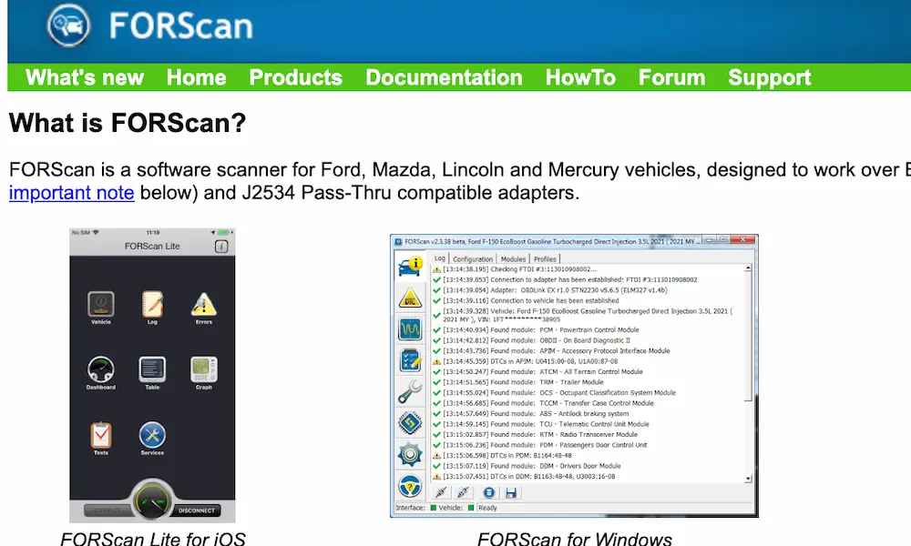
This is your primary diagnostic tool. A dealer-level scan tool monitors crankshaft rotational velocity in real time. Every cylinder that fires correctly causes a micro-acceleration. A dead or weak cylinder causes a tiny hesitation the computer catches and assigns to the specific cylinder scheduled to fire at that moment.
The Snap-on Diagnostics forum has solid context on how this test works in practice. The result is a bar graph showing each cylinder’s contribution. Low bars point you directly to the problem — no guessing which injector to pull.
Common Trouble Codes
- P0301–P0308 — Misfire detected in cylinders 1 through 8
- FICM circuit low codes — High resistance or broken circuit to an injector coil
- FICM performance code — Module can’t sustain 48-volt output; internal capacitor failure
Injector Stiction
Oregon Fuel Injection’s 6.0 diagnostic guide describes stiction as one of the most common firing-order disruptions on this engine. Degraded oil causes the internal spool valves inside each injector to stick.
The telltale signs:
- Hard cold starts
- Violent shaking for the first few minutes
- White smoke on startup that disappears once the engine warms up
As the oil heats up and thins, the stiction clears and the engine smooths out. That warm-up pattern is the classic stiction signature. Fresh, clean oil and a quality diesel fuel additive often resolve mild cases.
Two Critical Numbers During a No-Start
Riffraff Diesel’s scan tool data guide points to two live data readings that tell you everything during a crank-no-start:
- FICM voltage while cranking — Must stay at or above 45V, with 48V being ideal. Drop into the low 40s and the injectors won’t open, period.
- Injection control pressure (ICP) while cranking — Must hit 500 PSI minimum. Below that, you have a high-pressure oil leak. Common sources include worn injector O-rings, blown standpipe O-rings, failed dummy plug seals, or a failed snap-to-connect fitting on the HPOP discharge port (especially common on 2005–2007 engines).
6.0 Powerstroke vs. Other Power Stroke Generations
The 6.0 shares its firing order with the legendary 7.3 but differs from every Power Stroke that came after it.
| Engine | Production Years | Firing Order | Head Bolts/Cylinder | Fuel System |
|---|---|---|---|---|
| 7.3L Power Stroke | 1994.5–2003 | 1-2-7-3-4-5-6-8 | 6 bolts | HEUI Gen 1 |
| 6.0L Power Stroke | 2003–2007 | 1-2-7-3-4-5-6-8 | 4 bolts (TTY) | HEUI Gen 2 |
| 6.4L Power Stroke | 2008–2010 | 1-3-7-2-8-4-6-5 | 4 bolts | Common Rail |
| 6.7L Power Stroke | 2011–Present | 1-3-7-2-6-5-4-8 | 6 bolts | Common Rail |
The 7.3 and 6.0 share the same firing sequence because both use a cross-plane V-8 crankshaft with the same harmonic balancing theory. The 6.4 and 6.7 shifted firing orders as engineers redesigned the rotating assembly architecture entirely.
The Head Bolt Problem and the Firing Order Connection
Here’s something most owners don’t connect: the 6.0’s head bolt design directly affects the engine’s ability to maintain its firing order under load.
Each cylinder head uses only four torque-to-yield (TTY) head bolts. These bolts are designed to stretch elastically during installation to create precise clamping force. Under heavy boost or thermal stress, they can stretch past their elastic limit and lose clamping force permanently.
Once that clamping force drops, combustion pressure from the firing sequence physically lifts the cylinder head. The multilayer steel head gasket blows. Coolant enters cylinders. Hydro-lock follows.
The fix? Aftermarket head studs. This is the single most important modification on any 6.0 Power Stroke that hasn’t been done already. They replace the four factory TTY bolts with non-stretching studs that hold clamping force permanently — even under high boost.
The Cooling System Cascade Failure
Understanding the firing order also means understanding what kills the 6.0’s ability to execute it.
The failure chain goes like this:
- Residual casting sand in the block’s water jackets mixes with degraded coolant silicates
- That abrasive sludge clogs the oil cooler’s narrow internal passages
- Coolant stops flowing to the EGR cooler
- The EGR cooler overheats and its internal welds crack
- Coolant pours into the intake manifold
- The engine draws liquid into the combustion chamber on the intake stroke
- The piston hits incompressible liquid — hydro-lock — and destroys the head gasket
SPEtuner’s 6.0 buyer’s guide calls this the most documented failure chain on the entire platform. The solution is proactive: replace the OEM oil cooler with an upgraded unit, install a coolant filter, and use a quality diesel coolant additive to keep silicates in suspension.
Key Takeaways
The 6.0 Powerstroke firing order — 1-2-7-3-4-5-6-8 — isn’t just a number sequence to memorize. It’s the foundation of every diagnostic and mechanical decision you make on this engine. Odd cylinders live on the passenger side. Even cylinders live on the driver side. The sequence crosses the valley constantly to balance crankshaft loads and manage heat.
When this sequence breaks down, your scan tool’s cylinder contribution test points you to the exact problem cylinder. Your two live data numbers during a no-start — FICM voltage and ICP — tell you whether the issue is electrical or hydraulic before you touch a wrench.
And if you haven’t upgraded your head studs and oil cooler yet, those are the two jobs that keep the firing order running the way it’s supposed to.