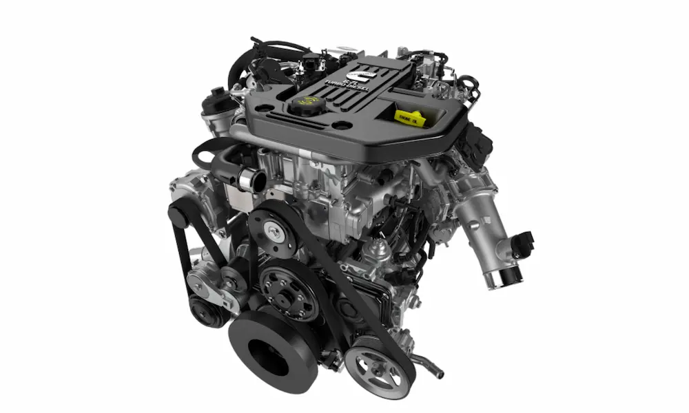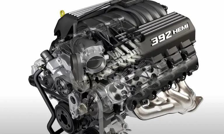
Got a misfire code? Replacing spark plugs? Or just want to understand what makes your Hemi tick — literally? This guide covers the 5.7 Hemi firing order, cylinder layout, ignition system, and the MDS failures that haunt owners. Stick around to the end — there’s some genuinely useful diagnostic stuff buried in here.
The 5.7 Hemi Firing Order Is 1-8-4-3-6-5-7-2
That’s it. Every 5.7 Hemi ever built uses this sequence: 1-8-4-3-6-5-7-2.
It hasn’t changed since the engine launched in 2003. Whether you’ve got a Ram 1500, a Dodge Challenger, a Jeep Grand Cherokee, or a Chrysler 300, the firing order stays identical.
Write it down. Take a photo. You’ll need it.
Where Are the Cylinders on a 5.7 Hemi?
Before the firing order means anything, you need to know where each cylinder actually sits.
The 5.7 Hemi is a V8, so it has two banks of four cylinders arranged in a V shape. Here’s how they break down:
- Bank 1 (Driver’s Side): Cylinders 1, 3, 5, 7 — running front to back
- Bank 2 (Passenger’s Side): Cylinders 2, 4, 6, 8 — running front to back
Cylinder 1 sits at the very front of the driver’s side, closest to the alternator and radiator. The even-numbered cylinders mirror them on the passenger side.
| Cylinder | Bank | Side (US Market) | Position |
|---|---|---|---|
| 1 | Bank 1 | Driver’s Side | Front |
| 2 | Bank 2 | Passenger’s Side | Front |
| 3 | Bank 1 | Driver’s Side | Second |
| 4 | Bank 2 | Passenger’s Side | Second |
| 5 | Bank 1 | Driver’s Side | Third |
| 6 | Bank 2 | Passenger’s Side | Third |
| 7 | Bank 1 | Driver’s Side | Rear |
| 8 | Bank 2 | Passenger’s Side | Rear |
This layout is the same across the entire third-generation Hemi family — 5.7, 6.1, 6.2 Hellcat, and 6.4 Apache. Same cylinder map, every time.
Why Does the Firing Order Matter So Much?
This isn’t just trivia. The firing order does three critical jobs:
- Balances the crankshaft so it doesn’t shake itself apart
- Routes ignition wiring — get it wrong and you’ll have misfires instantly
- Controls which cylinders the MDS shuts down (more on that below)
The Physics Behind 1-8-4-3-6-5-7-2
A four-stroke V8 takes two full crankshaft revolutions — 720 degrees — to complete one full cycle. Divide 720 by 8 cylinders and you get a power stroke every 90 degrees.
The 5.7 Hemi uses a cross-plane crankshaft, which is the classic American V8 design. Its four crank journals sit at 90-degree intervals. If you fired two cylinders on the same bank back-to-back, you’d destroy the crankshaft with localized torsional stress.
The 1-8-4-3-6-5-7-2 sequence deliberately jumps between banks and front-to-rear positions. It spreads the load evenly across the entire rotating assembly — no hot spots, no catastrophic twisting.
How It Compares to Other V8s
The Hemi isn’t alone in using this sequence. Classic GM small and big blocks used the exact same order. But modern engines have evolved:
| Engine Family | Firing Order | Cylinder Numbering |
|---|---|---|
| Chrysler 5.7/6.1/6.2/6.4 Hemi | 1-8-4-3-6-5-7-2 | Alternating (Odd driver, Even passenger) |
| Classic GM Small/Big Block | 1-8-4-3-6-5-7-2 | Alternating (Odd driver, Even passenger) |
| Modern GM LS Series | 1-8-7-2-6-5-4-3 | Alternating (Odd driver, Even passenger) |
| Legacy Ford Small Block | 1-5-4-2-6-3-7-8 | Sequential (Passenger 1-4, Driver 5-8) |
| Modern Ford Coyote V8 | 1-5-4-8-6-3-7-2 | Sequential (Passenger 1-4, Driver 5-8) |
Ford’s cylinder numbering looks completely different because they number cylinders sequentially down one bank before switching sides. That’s why their firing orders look alien compared to Mopar.
Why the 5.7 Hemi Has 16 Spark Plugs
Most V8s have 8 plugs. Your 5.7 Hemi has 16. Yes, really.
Every cylinder runs two spark plugs simultaneously. It sounds excessive until you understand how the hemispherical combustion chamber works.
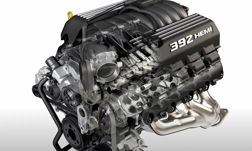
The dome-shaped chamber is what gives the engine its name and its power. The domed geometry keeps more heat inside the combustion event, which generates higher cylinder pressure and more torque. It also allows massive intake and exhaust valves to sit directly across from each other, letting the engine breathe freely.
The problem? Those big valves take up so much space that a single spark plug can’t sit in the center of the chamber. With one off-center plug, the flame front takes too long to travel across the full width of the dome — and incomplete combustion tanks your fuel economy while spiking emissions.
Two plugs firing from opposite sides solve this completely. Both spark plugs ignite the mixture simultaneously, creating two converging flame fronts that collide and consume the fuel almost instantly. The result is a sharper pressure spike, more torque, better throttle response, and cleaner exhaust.
It’s not a gimmick. It’s a legitimate engineering solution to a geometry problem.
The Ignition System: Waste Spark vs. Coil-on-Plug
The 5.7 Hemi’s ignition system changed significantly in 2006. Which version you have affects everything from maintenance to aftermarket upgrades.
2003–2005: Waste Spark System
Early Hemis used a hybrid setup. Each cylinder had one coil pack directly over one plug — but a long spark plug wire ran from that coil across the engine to a plug on a companion cylinder on the opposite bank.
The system fired both plugs simultaneously. One plug was on the compression stroke and ignited fuel. The other plug fired into exhaust gases — that’s the “wasted” spark. It worked, but those long crossover wires draped across a hot engine block degraded quickly. They built up resistance, complicated basic maintenance, and made the engine bay look like a wiring nightmare.
2006–Present: True Dual Coil-on-Plug
Starting in 2006, engineers ditched the crossover wires entirely. Each cylinder now gets its own independent dual-output coil pack sitting directly on the cylinder head, connected to both plugs via short silicone boots.
No long wires. No heat exposure. Maximum spark energy delivered exactly where it needs to go.
Factory coil packs output roughly 26.4 kilovolts and 35.8 millijoules of spark energy. Aftermarket performance coil packs — like those from RIPP — push that up to 27 kilovolts and 53.6 millijoules. That’s a 49% increase in spark energy, which translates to up to 20 additional horsepower on a naturally aspirated 5.7.
One thing to know: the 16 coils firing simultaneously generate serious radio frequency interference. The factory installs capacitors behind cylinders 7 and 8 specifically to absorb that electromagnetic noise and protect the crankshaft and camshaft position sensors from scrambled signals.
If you’re swapping to an aftermarket ECU like Holley or FAST XFI, you need the correct adapter harness — part number 558-311 for 2006+ coil-on-plug setups, and 558-310 for the early waste-spark configuration.
The MDS: How the Firing Order Controls Cylinder Deactivation
The Multi-Displacement System is directly tied to the 1-8-4-3-6-5-7-2 firing order. You can’t understand one without the other.
Under light load — highway cruising, steady throttle — the MDS shuts down four cylinders to save fuel. It specifically deactivates cylinders 1, 4, 6, and 7.
Look at the firing order: 1-8-4-3-6-5-7-2
The MDS deactivates every other cylinder in the sequence. Cylinders 2, 3, 5, and 8 stay active. Because the original firing order placed power strokes every 90 degrees, skipping every other one shifts the remaining four cylinders to fire every 180 degrees — perfectly symmetrical, no vibration. Fuel economy improves by an estimated 15–20%.
How Cylinder Deactivation Actually Works
Shutting off fuel and spark alone wouldn’t work. The cylinder would act like a massive air pump, creating pumping losses that kill any fuel savings.
Instead, specialized hydraulic lifters on the four target cylinders physically lock the valves shut. When the ECM commands deactivation, four solenoids under the intake manifold route pressurized oil into the lifters. That oil pressure collapses the locking pins inside the lifter, decoupling its inner and outer bodies. The camshaft lobe keeps spinning, the lifter body moves, but the pushrod stays still — the valves never open.
Trapped exhaust gas inside the sealed cylinder acts like a compressed air spring. The piston compresses it on the way up; it pushes back on the way down, recovering energy.
When you hit the throttle, the solenoids cut oil pressure in milliseconds, the pins re-engage, and the engine returns to full V8 power.
The Hemi Tick: What It Is and Why It Happens
The “Hemi tick” is the most notorious problem with this engine. It’s a distinct tapping or ticking sound from the top of the engine, and it almost always traces back to MDS lifter failure.
Those tiny locking pins inside the MDS lifters operate with microscopic clearances. They’re completely dependent on clean, correctly viscosity-rated oil delivered at adequate pressure. If oil quality drops, change intervals stretch too long, or the wrong viscosity gets used, sludge and varnish clog the oil galleries feeding the lifters.
Starved of pressure, the pins bind or collapse. The lifter loses structural rigidity. The camshaft lobe starts slapping against the loose lifter body on every single revolution. That metal-on-metal impact is your Hemi tick.
Ignore it long enough and the cam lobe’s surface hardening grinds away. Metal particles circulate through the entire engine. At that point, you’re looking at a complete top-end teardown — new lifters, new camshaft, new gaskets.
Prevention is straightforward:
- Use high-quality full synthetic oil — the correct viscosity for your model year
- Don’t extend oil change intervals
- Consider an aftermarket high-volume oil pump from Melling or the Hellcat-sourced units, which maintain better lifter pressure at low idle speeds
MDS Fault Codes to Know
If your scanner pulls any of these, cross-reference them against the 1-8-4-3-6-5-7-2 sequence to pinpoint the problem cylinder:
- P1414 — Cylinder 4 reactivation control failure
- P3400 — Cylinder deactivation system Bank 1 failure
- P3497 — Cylinder deactivation system Bank 2 failure
- P1411 — Cylinder 1 reactivation performance
- P0301 — Cylinder 1 misfire detected
- P0300 — Random multiple cylinder misfire (often contaminated oil or vacuum leak)
Disabling the MDS Without a Tune
You can’t permanently disable MDS by pressing the Tow/Haul button — that just changes shift points. The only reliable way to lock the engine in full V8 mode without aftermarket tuning software is to manually select a lower gear using the electronic range select. On older transmissions, select 4th. On newer units, try 8th. That keeps the system from meeting its activation conditions.
Performance Upgrades That Work With the Firing Order
The 5.7 Hemi responds well to modifications, especially when you work with its architecture rather than against it.
Cylinder head upgrades deliver the biggest naturally aspirated gains. Edelbrock’s performance heads (part number 61159 for 2009+ Eagle engines) feature 67cc combustion chambers, 202cc intake runners, and 2.165-inch intake valves. Pair them with long tube exhaust headers — which reduce backpressure from restrictive factory manifolds — and you’re looking at 10–35 horsepower depending on tune.
CNC block prep from builders like Arrington Engines ensures the deck surface is perfectly perpendicular to the main bearing line. Polished oil galleys mean faster fluid delivery to those sensitive MDS lifters — the same lifters that cause the ticking failures when neglected.
Upgraded coil packs are one of the easiest bolt-on wins. The jump from stock 35.8 millijoules to aftermarket 53.6 millijoules makes a real difference in flame propagation speed, particularly on forced induction builds.
The 5.7 also measures roughly 28 inches in total length, making it a popular engine swap candidate. With custom motor mounts and a standalone ECU that can run the sequential 1-8-4-3-6-5-7-2 injection and ignition timing, it drops into older chassis surprisingly well.
Where the 5.7 Sits in the Hemi Family
The 5.7’s firing order, ignition architecture, and MDS logic aren’t unique to this displacement. Every engine in the third-generation Hemi family shares the same foundation:
- 5.7L — 395 horsepower (Ram 1500, Charger, Challenger, Grand Cherokee)
- 6.4L Apache — 485–525 horsepower (heavy-duty platforms, SRT variants)
- 6.2L Hellcat — 707–717 horsepower (supercharged)
- 6.2L Demon — 840 horsepower
- D170 variant — 1,025 horsepower on specialized fuels
- Direct Connection 1500 crate engine — 1,500 horsepower, 1,000 lb-ft of torque
All of them fire in 1-8-4-3-6-5-7-2. All of them rely on the dual-spark ignition system, the cross-plane crankshaft balance, and the same basic hemispherical combustion chamber geometry that started with a WWII fighter plane engine. The 5.7 isn’t just a truck engine — it’s the baseline for one of the most developed performance architectures in American automotive history.