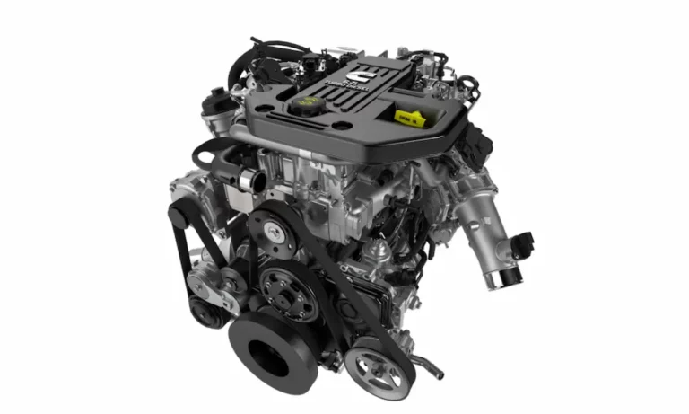
That ticking noise coming from your 6.7 Cummins isn’t going away on its own. Loose valve lash hammers your valvetrain into scrap metal. Tight lash burns exhaust valves and costs thousands. This guide walks you through the exact 6.7 Cummins valve adjustment procedure — specs, sequence, torque, and all the tricks pros use to get it right the first time.
What Is Valve Lash and Why Does the 6.7 Cummins Need It?
The 6.7 Cummins uses solid lifters instead of hydraulic lash adjusters. That means the engine can’t self-adjust the gap between the rocker arm and the crosshead bridge. You have to do it manually.
That gap is valve lash.
When the engine heats up, metal expands. The pushrods, rocker arms, crossheads, and valves all grow at different rates. Engineers build in a cold clearance so all that expansion doesn’t hold your valves open at operating temperature.
Get the gap wrong in either direction, and things go bad fast.
What Happens With Loose Valve Lash
- You hear a loud, rhythmic ticking — the classic “typewriter tick”
- The rocker arm slams across a wide gap instead of smoothly engaging
- Valve stems get peened, crossheads crack, and pushrod sockets wear unevenly
- Valves open late, don’t reach full lift, and close early
- You lose power, burn more fuel, and spike exhaust gas temperatures
The valve adjustment procedure for the QSB 6.7 confirms that loose lash directly reduces volumetric efficiency and increases turbo lag.
What Happens With Tight Valve Lash
Tight valves are quiet — and that’s exactly what makes them dangerous.
If the lash is too tight, thermal expansion forces the rocker arm to hold the valve slightly open. The cylinder can’t build compression. You get rough starts, misfires under load, and brutal power loss.
Exhaust valves suffer worst. They cool themselves by contacting the valve seat. Hold them off that seat and combustion gases act like a cutting torch, melting the valve edges. That’s a burnt valve — and a full cylinder head rebuild.
Don’t Confuse Valve Tick With Injector Tick
The 6.7 Cummins common rail injectors operate at extreme pressure and produce a sharp clicking sound that mimics valvetrain noise. Before you pull the valve cover, check your fuel system first. Monitor injector timing with a scan tool. If fuel system data looks clean and the ticking persists rhythmically with engine speed, it’s time for a valve inspection.
When to Perform a 6.7 Cummins Valve Adjustment
Cummins specifies valve lash inspection and adjustment at 150,000 miles. You also need to do it immediately after:
- Cylinder head replacement
- Head gasket repair
- Fuel injector replacement that required rocker arm removal
Don’t skip this step after a head job. The Fleece Performance Engineering cylinder head installation guide specifically calls out valve lash calibration as mandatory after any major top-end service.
Exact Valve Lash Specs for the 6.7 Cummins
These are the numbers you need. Set every valve to the nominal target — don’t aim for the middle of the acceptable range.
| Valve Type | Nominal Target | Minimum Limit | Maximum Limit |
|---|---|---|---|
| Intake | 0.010 inches | 0.006 inches | 0.022 inches |
| Exhaust | 0.020 inches | 0.015 inches | 0.032 inches |
Setting to nominal spec reduces valvetrain noise and extends component life. The 6.7 Cummins valve adjustment guide on Scribd confirms these as the factory baseline targets for both the automotive and marine QSB 6.7 platforms.
Tools You Need Before You Start
Don’t start disassembly without these:
- Engine barring tool (Cummins Part Number 3824591) — inserts into the flywheel housing and lets you rotate the crankshaft by hand
- Precision feeler gauges — 0.010 inch and 0.020 inch blades, angled design preferred
- Low-range inch-pound torque wrench — for injector nuts (13 in-lb) and valve cover bolts (216 in-lb)
- Mid-range foot-pound torque wrench — for rocker pedestals (27 ft-lb) and locknuts (18 ft-lb)
- 14mm box-end wrench
- Flat-blade screwdriver
- High-visibility paint marker — to mark adjusted rockers and track your progress
Critical Pre-Service Rules
The Engine Must Be Cold
The factory protocol is absolute: engine coolant temperature must be below 140°F before you take any measurements. Adjusting on a heat-soaked engine means the components are thermally expanded. When they cool, the lash opens up wider than your target and the ticking returns immediately on the next cold start.
Let the engine sit overnight in a temperature-controlled space. Don’t rush this.
Disconnect Both Batteries
Cut the negative cables from both batteries before touching anything. This prevents the starter from engaging while your hands are in the valvetrain, and protects the injector wiring harnesses from electrical damage.
Disassembly: Getting to the Valvetrain
Handle the CCV System Carefully
The 6.7 Cummins mounts its Crankcase Ventilation filter directly on top of the valve cover. Disconnect the hoses running to the turbo inlet, unbolt the plastic top cover, and pull the internal filter element. Replace it now — a clogged CCV builds crankcase pressure that blows seals and causes oil leaks down the sides of the engine.
If your setup uses an aftermarket CCV reroute delete plate, disconnect those components per the kit instructions. This modification eliminates oily sludge buildup on the turbo compressor blades and keeps your intake tract clean.
Handle the Injector Harness With Extreme Care
The fuel injector wiring passes through sealed pass-throughs in the valve cover. The retaining nuts on those terminals are rated to just 13 inch-pounds. Use a calibrated inch-pound torque wrench — not a standard ratchet, not a hand-tight guess. Strip those threads and you’re replacing an entire injector assembly.
Removing the Valve Cover
Once all wiring, ventilation components, and brackets are clear, loosen the perimeter valve cover bolts systematically. Lift the cover straight up. At the rear of the engine near cylinders 5 and 6, clearance to the firewall is extremely tight.
Dragging the cover against the firewall damages the reusable rubber gasket and drops debris directly into the exposed valvetrain. Use a telescoping mirror and flashlight to check the rear gasket edge before reinstalling.
Inspect the gasket for rolled edges, flat spots, or hardened sections. Replace it if it shows any of those signs.
Finding Top Dead Center
The 6.7 Cummins requires two full crankshaft rotations (720 degrees) to complete one full engine cycle. You can only adjust a cylinder’s valves when that piston sits at Top Dead Center on the compression stroke — the exact point where both lifters rest on the base circle of the camshaft lobes with maximum slack in the system.
Using the Vibration Damper
Insert the barring tool into the flywheel housing access port. Rotate the crankshaft clockwise (viewed from the front). Watch the timing mark on the vibration damper. Align the TDC mark to the 12 o’clock position pointing straight up.
Confirming the Compression Stroke
The damper mark at 12 o’clock puts piston 1 at the top — but it could be on the compression stroke or the exhaust stroke. Check by grabbing the intake and exhaust rockers for cylinder 1 (closest to the fan). If both rockers have slight play and wiggle freely, cylinder 1 is on the compression stroke. You’re ready for Pass 1.
If both rockers are tight and under spring tension, cylinder 1 is in valve overlap. Rotate the crankshaft a full 360 degrees to bring the mark back to 12 o’clock, then recheck.
The Companion Cylinder Method
Master mechanics use this trick to confirm base circle without relying on timing marks that may be rusty or worn. On an inline-six, companion cylinder pairs are 1 & 6, 2 & 5, and 3 & 4. When cylinder 1 is at TDC compression, cylinder 6 is at overlap.
Watch cylinder 6’s rockers while slowly barring the engine. When you see the exhaust rocker coming up and the intake rocker going down at the same time — that’s the crossover point. At that exact moment, cylinder 1 is at TDC compression. This method relies directly on camshaft geometry, not painted lines.
The Two-Pass Adjustment Sequence
The 6.7 Cummins fires in the order 1-5-3-6-2-4. You can’t adjust all 24 valves at once. Cummins engineers designed a two-pass system that covers the entire engine with just one crankshaft rotation.
Pass One: Cylinder 1 at TDC Compression
With the damper mark at 12 o’clock and cylinder 1 rockers loose, adjust these valves:
| Cylinder | Intake (0.010″) | Exhaust (0.020″) |
|---|---|---|
| 1 | ✅ | ✅ |
| 2 | ✅ | — |
| 3 | — | ✅ |
| 4 | ✅ | — |
| 5 | — | ✅ |
| 6 | Skip | Skip |
Mark each adjusted rocker with a paint marker as you go. It prevents double-adjusting or skipping a valve.
Pass Two: Cylinder 6 at TDC Compression
Remove all tools from the top of the engine. Use the barring tool to rotate the crankshaft exactly 360 degrees clockwise. Return the damper mark to 12 o’clock. Now cylinder 6 rockers will be loose. Adjust the remaining valves:
| Cylinder | Intake (0.010″) | Exhaust (0.020″) |
|---|---|---|
| 1 | Skip | Skip |
| 2 | — | ✅ |
| 3 | ✅ | — |
| 4 | — | ✅ |
| 5 | ✅ | — |
| 6 | ✅ | ✅ |
All 24 valves are now set.
How to Actually Use the Feeler Gauge
Slide the correct blade flat and parallel between the rocker arm adjusting screw and the crosshead pad. Don’t bend it. Don’t angle it. Any twist generates false friction and makes the gap feel tighter than it is.
The target sensation is a slight drag when pulling the blade through. Zero resistance means it’s too loose. The gauge buckling or scratching metal means it’s too tight.
Locking the Adjustment Without Losing It
- Loosen the 14mm locknut on the rocker arm
- Hold the flat-blade screwdriver on the adjustment screw
- Turn the screw clockwise to tighten, counterclockwise to loosen
- Achieve the target drag with the gauge in place
- Hold the screw completely still while you snug the locknut
Here’s the critical part: thread pull. As the locknut cinches down, it pulls the adjustment screw upward slightly. This almost always tightens the lash by a small but measurable amount.
Many experienced techs set the initial clearance fractionally loose to account for this. Regardless of technique, the non-negotiable rule is: verify the feeler gauge drag after the locknut reaches final torque. If it’s bound tight, back off and restart that valve.
Fastener Torque Specs
Get these wrong and you’ll snap studs, strip threads, or watch the valve cover leak oil from day one.
| Component | Torque Spec |
|---|---|
| Valve lash locknuts | 212 in-lb (18 ft-lb) |
| Rocker arm pedestal bolts | 27 ft-lb |
| Valve cover perimeter bolts | 18 ft-lb (216 in-lb) |
| Injector harness pass-through nuts | 13 in-lb |
| Injector hold-down bolts | 89 in-lb |
| Standard cylinder head bolts | 66 ft-lb + 90° rotation |
The Cummins engine torque specs resource at Diesel Pro Power emphasizes that confusing inch-pounds with foot-pounds is the most common cause of snapped bolts and stripped cast aluminum threads during top-end service. Always confirm your wrench range before torquing.
Important: Torque the rocker pedestal bolts to 27 ft-lb before measuring valve lash. Seating the pedestal changes the rocker arm’s height relative to the crosshead. Measure after pedestal torque, not before.
Reinstalling the Valve Cover
Clean the aluminum mating surface completely. Any residual oil or silicone creates a channel for pressurized crankcase oil to escape.
Lower the valve cover straight down and horizontal. Use a mirror and flashlight to confirm the rear gasket — near cylinders 5 and 6 — seats fully in its channel before threading a single bolt. A gasket that rolls out at the rear isn’t visible from the front of the engine bay until oil runs down the firewall.
Torque the perimeter bolts using a center-out crisscross pattern in three passes:
- Pass 1: Hand-thread all bolts to prevent cross-threading
- Pass 2: Snug all bolts in center-out crisscross sequence with a hand ratchet
- Pass 3: Final torque at 18 ft-lb in the same center-out sequence
Never torque a leaking valve cover tighter to fix a leak. A crushed or hardened gasket needs replacement. Over-torquing warps the plastic cover and pulls aluminum threads.
Post-Adjustment Startup Check
Reconnect both batteries. Start the engine and let it idle to full operating temperature without touching the throttle.
A correctly adjusted valvetrain sounds smooth and uniform — like a sewing machine. The typewriter ticking disappears completely. Throttle response sharpens noticeably.
While it warms up, inspect the valve cover perimeter, injector pass-throughs, and CCV housing for any oil seepage. A fresh gasket seated correctly won’t leak.
If the engine idles rough, loses power, smokes heavily, or triggers a cylinder misfire code immediately after the adjustment — shut it down. Those symptoms indicate a valve set too tight, holding it off the seat. Pull the valve cover, let the engine return to ambient temperature, and re-verify all 24 valves before running it again.
Performance Engines: Fire Rings and Head Studs
If your 6.7 Cummins runs upgraded ARP head studs or solid metal fire ring head gaskets for high-boost applications, the valve adjustment procedure adds one more step.
As fire rings crush and seat after the first heat cycles, the cylinder head physically sinks toward the block. This pushes rocker arms upward and tightens all your lash settings. After any hot re-torque sequence on performance hardware, you must recalibrate the valve lash from scratch. Skip this step and you’ll burn exhaust valves faster than you can rebuild the head.