Your 6.7 Powerstroke is misfiring, blowing smoke, or chugging through fuel like it’s free. Sounds like a bad injector. This guide walks you through the full 6.7 Powerstroke injector removal process — from diagnosis to IQA coding — so you don’t waste money guessing or pay someone else to do it wrong. Read to the end. The last step trips up even experienced techs.
Why the 6.7 Powerstroke Makes Injector Work Manageable
Ford’s reverse-flow “Hot-V” architecture was a smart engineering move. It put the exhaust ports in the engine valley and pushed the turbo into the center. That freed up the outer banks for the fuel rails and injectors.
The result? The injectors sit on the outside of the cylinder heads. You don’t pull the main valve covers to reach them. Compare that to the 6.0 or 6.4 Powerstroke, where injectors were buried under oil rails, harnesses, and wiring. The time savings on the 6.7 are significant.
That said, “accessible” doesn’t mean easy. The engine bay is packed tight. Certain cylinders still require major teardown to reach.
Know Your Cylinder Layout Before You Touch Anything
The 6.7 Powerstroke is a 90-degree V8. Ford numbers cylinders sequentially down each bank — not alternating across both sides.
| Bank | Chassis Location | Cylinders (Front to Rear) |
|---|---|---|
| Bank 1 | Passenger Side | 1, 2, 3, 4 |
| Bank 2 | Driver Side | 5, 6, 7, 8 |
Cylinder 1 sits at the front passenger side near the radiator. Cylinder 8 hides at the rear driver side, tucked under the firewall. Knowing this upfront saves you from tearing into the wrong side of the engine.
How to Diagnose a Bad Injector First
Don’t pull injectors on a hunch. These parts are expensive, and a wrong guess wastes hours of labor.
Scan Tool Contribution Testing
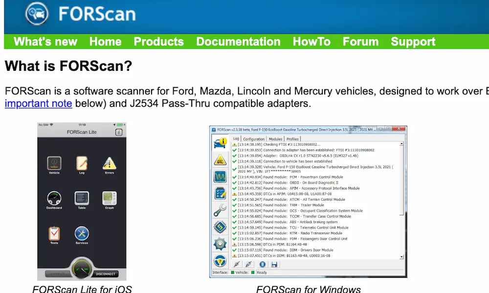
Grab a professional scan tool — FORScan works well and it’s affordable. The PCM watches crankshaft speed constantly. When a cylinder fires weakly, the crank slows slightly. FORScan catches these micro-dips and shows them as cylinder contribution balance rates.
A cylinder showing a consistently negative value is often dealing with internal stiction in the piezoelectric control valve. It can’t open or close fast enough.
Physical Symptoms to Watch For
| Symptom | What You’ll See | What’s Actually Wrong |
|---|---|---|
| Exhaust smoke | White or black smoke, especially cold or under load | Nozzle worn or stuck open — fuel leaks into the cylinder when it shouldn’t |
| Fuel in the oil | Oil level rising, smells like diesel | Raw fuel is bypassing piston rings and diluting your oil — this destroys bearings fast |
| Oil leak at injector base | Oil running down the block near the injector | The rubber injector-to-valve-cover seal has shrunk or cracked — often misdiagnosed as a valve cover gasket issue |
| Hard starting / long crank | Won’t fire easily, low rail pressure codes | Internal leakage in worn injectors — the pump can’t hold minimum start pressure |
Return Flow Testing
This test proves internal leakage definitively. Disconnect the low-pressure return rail and attach a measuring cylinder to each injector’s return port. Idle the engine for one minute. Measure the fuel that bleeds out.
Any injector that dumps significantly more fuel than its neighbors has failed internally. Replace it.
Accessing the Injectors: Driver Side vs. Passenger Side
Driver Side — Bank 2 (Cylinders 5–8)
This side is the easier one, but it still demands careful work.
Your main obstacle is the crankcase ventilation (CCV) filter housing. This large plastic assembly sits directly above the valve cover. Remove it by disconnecting the battery, pulling the charge air cooler intake pipe, and unbolting the housing from the engine.
You’ll also need to reposition:
- Fuel filter inlet tubes
- Fuel return quick-connect couplings
- Engine oil dipstick tube
Pro tip: Pull the driver side inner fender liner. It opens up lateral access under the steering shaft and brake master cylinder, making tool manipulation much easier.
Passenger Side — Bank 1 (Cylinders 1–4)
This side is the harder job — full stop. The EGR cooler sits directly on top of the passenger side valve cover.
Before you can see those injectors, you need to:
- Drain the secondary cooling system (manages the charge air cooler and EGR cooler)
- Pull the intake air box, MAF sensor, and intake piping
- Unbolt and shift the PCM aside to protect its wiring harness
- Unbolt the EGR cooler from the exhaust manifold and engine block
Only then do the fuel rails, supply tubes, and injectors for Bank 1 become fully visible.
Safety and Depressurization — Don’t Skip This
The Bosch common rail system runs up to 30,000 PSI. That pressure stays in the lines even after shutdown. High-velocity diesel spray at that pressure can puncture skin and cause serious injury.
Follow this sequence every time:
- Cycle the ignition off and listen for the frame-rail lift pump to stop
- Wait a minimum of 5 minutes — internal valving bleeds residual pressure back into the return circuit
- Disconnect both batteries at the negative terminals
- Clean everything around the injector area with compressed air and solvent before loosening any fittings
- Cap all open ports immediately after removal — contamination destroys these components fast
The Physical Removal Process
Because the 6.7 Powerstroke injectors face the ambient environment instead of bathing in warm oil, they corrode. Road salt, moisture, and carbon build up in the cylinder head bore and lock the injector in place. Getting the injector loose is often the hardest part of the whole job.
Each injector uses a steel hold-down clamp secured by a single torque-to-yield bolt. Remove the bolt, disconnect the high-pressure supply tube and electrical connector — and then the real fight begins.
Specialized Extraction Tools
The factory-approved method uses Ford tool 310-230. It threads into the hold-down bolt hole and pulls the injector straight up using a forcing screw. The perfectly vertical pull is critical — any lateral angle risks fracturing the aluminum cylinder head.
For badly seized injectors, the ProMAXX PowerPull system adds a precision-machined lift pad that prevents the tool from walking across the head surface. It delivers smooth, high-tension vertical force without flexing.
Field Methods Without Special Tools
No bridge tool? Two proven field techniques:
Inverted clamp method: Flip the hold-down clamp upside down and loosely thread the bolt back into the head. Position a pry bar under one end of the inverted clamp and strike firmly with a hammer. The clamp acts like a seesaw — downward force on one side translates into an upward pop on the injector lip. This works surprisingly well on moderately seized injectors.
Old fuel line method: An old high-pressure supply line shares the same thread pitch as the injector inlet. Thread a cut section of old line onto the injector, notch the tube, hook a pry bar through the notch, and use the cylinder head edge as a pivot. Pull perfectly straight upward — no lateral movement.
When the Injector Won’t Budge
On high-mileage trucks from cold climates, static pulling sometimes fails. Don’t keep cranking the forcing screw — you’ll snap the top off the injector and make your day much worse.
The solution is kinetic shock. Thread a heavy slide hammer attachment onto the injector’s fuel inlet — a standard lug nut occasionally shares the thread pitch and works in a pinch. Aggressive upward impacts shatter the rust and carbon bond without fracturing the head. Advanced kits combine static lifting tension with air hammer vibration simultaneously for the toughest extractions.
Seat Machining — The Step Most People Skip
Once the injector is out, look down into the bore. At the bottom sits a copper crush washer. That washer seals combustion pressure away from the injector body. When it fails or degrades, hot exhaust gas pushes carbon particulates up into the bore. The carbon hardens into a crust that pits the aluminum seating surface.
Installing a new injector on a pitted seat means instant seal failure. You’ll hear ticking immediately, lose compression, and start the whole job over.
Brass wire brushes don’t fix this. Brass is softer than baked carbon — it polishes the crust instead of cutting it. Use a proper seat machining tool designed for the 6.7 Powerstroke. The hardened steel cutters shave carbon and a microscopic layer of aluminum — usually no more than 3 thousandths of an inch — restoring a perfectly flat seating surface. The whole operation takes seconds, and the tool works with the valve cover still on.
Reassembly and Torque Specifications
Install a new copper crush washer, a new O-ring on the injector body, and a new valve cover seal (Ford part BC3Z-6C535-A). Lightly oil the O-rings before inserting. Push the injector down firmly until the copper washer contacts the freshly machined seat.
Now torque everything correctly.
| Fastener | Stage 1 | Stage 2 | Reuse? |
|---|---|---|---|
| Injector Hold-Down Bolt | 22 ft-lbs (30 Nm) | + 90° rotation | No — single use only |
| Fuel Rail Mounting Bolts | 18 ft-lbs (24 Nm) | N/A | Yes |
| High-Pressure Supply Tube | 177 in-lbs (20 Nm) | 26 ft-lbs (35 Nm) | No — single use only |
The hold-down bolt is a torque-to-yield fastener. It permanently stretches during installation. Reusing a stretched bolt gives insufficient clamping force and leads directly to blow-by and injector damage.
The high-pressure supply tubes are also one-time-use. The metal flare deforms to match its specific mating surface on first installation. Reusing old tubes creates invisible micro-leaks that cause rail pressure drop and hard starting.
Supply tube installation sequence:
- Slightly loosen the fuel rail mounting bolts to allow micro-adjustment
- Thread both ends of the new tube fully by hand — no cross-threading
- Pre-tighten both ends to 177 in-lbs (20 Nm)
- Torque the fuel rail bolts to 18 ft-lbs (24 Nm)
- Final torque the supply tube to 26 ft-lbs (35 Nm)
IQA Coding — The Step That Can Ruin a Perfect Job
Physical installation is only half the work. Every 6.7 Powerstroke injector gets flow-tested at the factory. Its exact performance characteristics — across multiple pressure ranges and pulse widths — get encoded into a unique 10-digit alphanumeric IQA code laser-etched onto the injector body. This code tells the PCM precisely how to compensate for that specific injector’s real-world behavior.
If you install a new injector and skip this step, the PCM keeps using the dead injector’s old calibration data. The new hardware gets fed wrong pulse widths. The result is rough idle, increased smoke, poor fuel economy, cylinder imbalance codes, and a check engine light.
How to enter IQA codes:
- Read and record the 10-digit code from the new injector before it goes in — use a mirror or inspection camera for tight cylinders
- Reconnect the batteries and plug a scan tool into the OBD-II port
- Open FORScan or Ford IDS/FDRS and navigate to the PCM programming menu
- Select the correct cylinder number
- Enter the new IQA code and save it to the PCM
- Reset the PCM’s minimum fuel mass adaptations and clear learned injection correction factors for the replaced cylinder
This forces the computer to abandon its old learned habits and adapt fresh to the new hardware. Dealers use IDS; FORScan handles this job too at a fraction of the cost.
Priming and First Start
Before cranking, check for fluid in the cylinder. When you pulled the injector, residual fuel and oil from the valve train area may have drained into the combustion chamber. Liquids don’t compress. Cranking with fluid trapped in the cylinder bends rods and cracks blocks.
Remove the glow plug for the affected cylinder. Gently rest the valve cover in place and rotate the crankshaft by hand through a full cycle, or bump the starter for a few revolutions. The rising piston pushes the trapped fluid out through the open glow plug hole harmlessly. Reinstall and torque the glow plug before moving on.
Now prime the fuel system:
- Cycle the ignition to ON — don’t crank
- The low-pressure lift pump runs for 30 seconds, pushing fuel up to the high-pressure pump
- Repeat this cycle at least three times
On first start, expect extended cranking while the high-pressure pump purges air from the supply tubes and rails. Once rail pressure crosses the PCM’s minimum threshold, the engine fires. Long first-crank time after injector work is normal — it’s not a sign something went wrong.