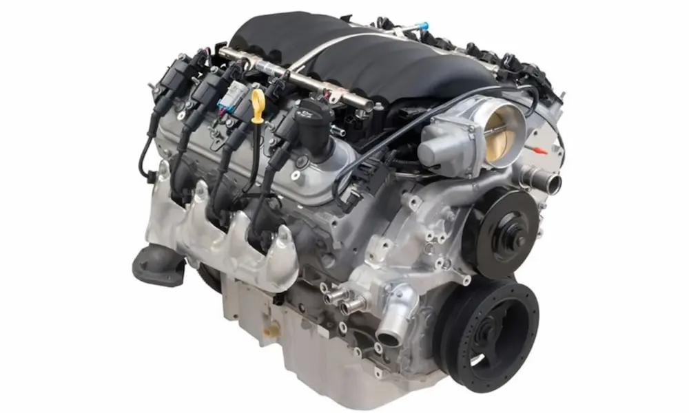
Got a Chevy 350 and staring at a distributor cap like it owes you money? Whether you’re chasing a rough idle, building a performance engine, or just want to understand what makes this legendary V8 tick — you’re in the right place. This guide covers the standard firing order, cylinder layout, performance swaps, marine applications, and more. Stick around because the details at the end could save your engine.
What Is the Chevy 350 Firing Order?
The Chevy 350 firing order is 1-8-4-3-6-5-7-2.
That’s the standard sequence for every Gen I small block Chevrolet — including the 283, 302, 305, 327, 350, and 400 cubic inch engines. It’s been the same since 1967, and it works because engineers designed it that way on purpose.
The distributor rotor spins clockwise when viewed from above. Get that backward and you’ll have a backfiring, rough-running mess on your hands.
Chevy 350 Cylinder Numbering: Where Are the Cylinders?
Before you touch a single spark plug wire, you need to know the layout.
The Chevy small block uses a 90-degree V8 configuration. Cylinder numbering follows this pattern:
- Driver side (Bank 1): Cylinders 1, 3, 5, 7 — front to back
- Passenger side (Bank 2): Cylinders 2, 4, 6, 8 — front to back
- Cylinder #1 is always at the front of the driver’s side
The driver side sits slightly forward because two connecting rods share each crankshaft journal. That offset pushes Bank 1 ahead, making cylinder 1 the forward-most position on the left.
Here’s how Chevy compares to other manufacturers:
| Manufacturer | Bank 1 Location | Numbering Pattern |
|---|---|---|
| Chevrolet (Small Block) | Driver Side | Left: 1-3-5-7 / Right: 2-4-6-8 |
| Ford (Traditional V8) | Passenger Side | Right: 1-2-3-4 / Left: 5-6-7-8 |
| Chrysler (Small Block) | Driver Side | Left: 1-3-5-7 / Right: 2-4-6-8 |
Misidentify cylinder 1 and everything else falls apart.
Why This Specific Firing Order?
The 1-8-4-3-6-5-7-2 sequence isn’t random — it’s carefully engineered to keep the engine alive.
A V8 completes all eight combustion events over 720 degrees of crankshaft rotation. Four crankshaft journals mean pistons work in pairs. In the Chevy 350, the paired cylinders are:
- 1 and 6
- 5 and 8
- 4 and 7
- 2 and 3
When one piston in a pair reaches top dead center on compression, its partner hits top dead center on the exhaust stroke. They swap roles after every 360 degrees.
The 1-8-4-3-6-5-7-2 sequence fires each cylinder 90 degrees of crankshaft rotation apart. It deliberately avoids firing adjacent cylinders back-to-back — spreading combustion forces evenly across the block. Skip this logic and you get asymmetric force, worn main bearings, and violent engine shake.
How to Wire the Distributor Cap Correctly
This is where most DIY mistakes happen. Follow these steps:
- Manually rotate the engine until cylinder 1 reaches top dead center on the compression stroke
- Locate which terminal on the distributor cap aligns with the rotor contact — that’s cylinder 1’s terminal
- Route the cylinder 1 wire to that terminal
- Continue wiring in the 1-8-4-3-6-5-7-2 sequence clockwise around the cap
Two swapped wires can cause backfiring, rough idle, hesitation under acceleration, and — worst case — pre-ignition detonation against a rising piston. Don’t guess. Verify before you start the engine.
Spark Plug Wire Routing: Don’t Ignore Crossfire
Here’s something most guides skip over — and it costs people engines.
When high-voltage current travels through a spark plug wire, it generates an electromagnetic field. If two wires run parallel and close together, that field can induce a rogue electrical current in the neighboring wire. That’s called crossfire, and it’s a real problem on the driver side of the Chevy 350.
Why? Because cylinders 5 and 7 fire back-to-back in the standard sequence. Their wires run right alongside each other on the driver side valve cover. If those wires are zip-tied together or routed parallel, cylinder 5’s pulse can trigger a premature spark in cylinder 7 — while that piston is still coming up on compression. The result is detonation that fights the piston directly. Think blown head gaskets and shattered ring lands.
How to prevent crossfire:
- Never route consecutive firing wires parallel to each other
- Cross wires at 90-degree angles to break the induction field
- Use plastic or rubber wire separators to maintain an air gap
- Choose spiral core or resistor core wires — they suppress electromagnetic interference far better than solid core wires
- Use the shortest possible wire for each cylinder to reduce exposure
- Route wires away from exhaust manifolds and headers — heat destroys insulation fast
Neat wire routing looks great. But neat and parallel can destroy your engine. Cross those wires.
The 4/7 Firing Order Swap: A Performance Upgrade Worth Knowing
The stock 1-8-4-3-6-5-7-2 firing order served millions of street cars just fine. But in racing? Engineers found a real problem.
Cylinders 5 and 7 sit at the rear of the driver’s side bank — and they fire consecutively. At high RPM, that creates:
- Intense localized heat trapped in the rear left corner of the block
- Intake reversion in the manifold as adjacent valves open in rapid succession
- Torsional stress concentrated at the rear of the crankshaft — near the flywheel
The fix? Swap cylinders 4 and 7 on the camshaft.
Since cylinders 4 and 7 share the same crankshaft journal, their roles in the combustion cycle can be reversed without a new crank. A specialty camshaft does the work. Re-route the spark plug wires and the new firing order becomes:
1-8-7-3-6-5-4-2
Now the back-to-back firing moves to cylinders 4 and 2 at the front of the passenger side — right next to the water pump. Coolest part of the engine. Coolest coolant. That moves heat away from the rear bank, allows more ignition timing advance, and consistently improves mid-range horsepower.
Structural benefits are just as significant. Moving consecutive firing events to the front of the block reduces camshaft twist, balances rod bearing loads more evenly, and cuts main bearing wear across thousands of hard passes on a drag strip.
The 4/7 swap is now widely available in Stage 1 through Stage 8 hydraulic flat tappet and roller camshafts for street and strip applications. No block modifications required.
The LS Firing Order: GM’s Factory Upgrade
GM took the 4/7 swap idea and pushed it further when they designed the LS platform in 1997.
Engineers used computer modeling to analyze bearing wear patterns and vibration harmonics. They added a second swap — cylinders 2 and 3 — to the 4/7 modification. The result is the modern LS firing order:
1-8-7-2-6-5-4-3
Here’s how the three sequences compare:
| Engine Platform | Firing Order | Back-to-Back Firing Location |
|---|---|---|
| Traditional Small Block Chevy | 1-8-4-3-6-5-7-2 | Rear left (cylinders 5 then 7) |
| 4/7 Swap Modification | 1-8-7-3-6-5-4-2 | Front right (cylinders 4 then 2) |
| Modern LS Engine | 1-8-7-2-6-5-4-3 | Front left (cylinders 3 then 1) |
The LS sequence delivers the smoothest energy transfer across the full crankshaft length. It also stabilizes the reluctor wheel at the rear of the crank, preventing false misfire codes from the crankshaft position sensor.
Good news for vintage 350 builders — you can buy an LS-spec camshaft ground specifically for Gen I blocks. No machining needed. Install the cam, re-route the plug wires in the 1-8-7-2-6-5-4-3 sequence clockwise on the distributor cap, and tape a label on the distributor. Anyone working on it later needs to know the sequence changed — or they’ll wire it wrong and wonder why it won’t run.
Chevy 350 Firing Order in Marine Applications
Twin-engine boats add a layer of complexity that’s easy to underestimate.
If both engines spin in the same direction, combined propeller torque constantly pushes the stern sideways — a problem called prop walk. It makes docking a nightmare. The fix is running the starboard engine in standard rotation and the port engine in reverse rotation.
Reversing a four-stroke engine requires:
- A mirror-image camshaft with reversed lobe profiles
- Reversed crankshaft rotation (counterclockwise from the front)
- A custom marine timing set if chain-driven — so the distributor still spins clockwise
- A completely different firing order: 1-2-7-5-6-3-4-8
That reverse marine firing order comes directly from tracing the standard 1-8-4-3-6-5-7-2 sequence backward around the distributor cap.
| Rotation Type | Crankshaft Direction | Distributor Rotation | Firing Order |
|---|---|---|---|
| Standard (Automotive / Marine LH) | Clockwise | Clockwise | 1-8-4-3-6-5-7-2 |
| Reverse (Marine RH) | Counter-Clockwise | Clockwise | 1-2-7-5-6-3-4-8 |
Marine timing also requires special attention. The factory timing tab only works for standard rotation. On a reverse-rotation engine, you mark the harmonic balancer manually — scribing timing marks on the opposite side of the standard notch to set base timing accurately.
The Gen II LT1 Optispark: When Chevy Went Optical
In 1992, Chevy introduced the LT1 350 in the Corvette with a radically different ignition system — the Optispark distributor.
The firing order stayed at 1-8-4-3-6-5-7-2. But the delivery system changed completely.
Instead of a magnetic reluctance trigger mounted at the top rear of the block, the Optispark used an optical sensor with a two-track slotted disk:
- Low-resolution track: 8 slots of varying width — identifies which cylinder is approaching combustion
- High-resolution track: 360 slots — lets the ECU track crankshaft angle in 1-degree increments
The result? The ECM could time each cylinder individually. If a knock sensor detected pre-ignition in one cylinder, the computer retarded timing for that cylinder alone — leaving the other seven running at peak power.
Cold starts improved dramatically. A magnetic system needed roughly 4 seconds of cranking at -35°C. The Optispark fired in 1.5 seconds.
The unit mounted low on the front timing cover, driven by the camshaft. That placement created one notorious vulnerability — it sat directly below the water pump. A leaking water pump bearing drains coolant straight onto the optical sensor. Early 1992-1993 units were completely unvented, trapping condensation and corrosive ozone inside.
GM fixed this in 1994 by adding vacuum vents that pulled fresh air through the cap and routed gases into the intake manifold. When replacing an Optispark, torque the mounting bolts to exactly 8 foot-pounds — over-tightening cracks the housing and destroys the optical disk.
For standalone ECU setups like Haltech systems, the wiring pinout matters:
| Pin | Signal | ECU Connection |
|---|---|---|
| A | 8x Low-Resolution Signal | Primary Trigger Input |
| B | 360x High-Resolution Signal | Engine Home Input |
| C | 12V Switched Positive | Ignition Switch Power |
| D | Signal Ground | ECU Ground |
The Sound of the Chevy 350: Cross-Plane Physics
That iconic burble — the deep, uneven V8 rumble — isn’t a coincidence. It’s physics.
The cross-plane crankshaft spaces crank pins 90 degrees apart. Mathematically, it’s impossible to perfectly alternate firing between left and right banks throughout the full cycle. In the LS firing order, two right-bank cylinders fire consecutively — creating a double exhaust pulse on the passenger side. That’s the burble.
A flat-plane crankshaft (like the Ferrari V8 or the Ford GT350) spaces pins 180 degrees apart. It fires perfectly left-right-left-right throughout the cycle — creating a high-pitched, smooth scream instead of a rumble.
Flat-plane cranks excel at high-RPM scavenging. But they introduce severe secondary vibration imbalances. For torque-heavy street, tow, and marine applications, the cross-plane design wins — and a well-chosen firing order manages the inherent bank-to-bank irregularity as effectively as possible.
Understanding the Chevy 350 firing order means understanding a century of engineering compromise, motorsport discovery, and relentless refinement — all packed into one cast-iron block that refuses to go away.