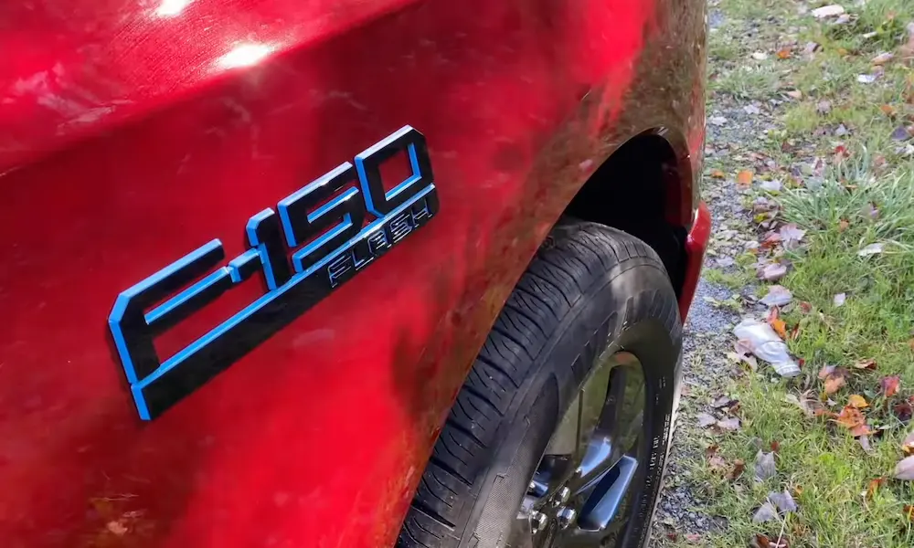
Got a Ford F-150, Expedition, or E-Series van with a 5.4 Triton under the hood? Then you’ve probably dealt with a rough idle, a misfire code, or a spark plug that fought back hard. This guide breaks down the Ford 5.4 firing order, cylinder layout, ignition system, and the chronic issues that plague this engine — so you can fix it right the first time.
What Is the Ford 5.4 Firing Order?
The Ford 5.4 firing order is 1-3-7-2-6-5-4-8.
That’s the exact sequence the ignition system uses to fire each cylinder. It never changes — doesn’t matter if it’s a 1997 F-150 or a 2014 Expedition. The two-valve, three-valve, and four-valve versions all share this same sequence.
This firing order is also shared with the 4.6L Modular V8. Both engines trace this sequence back to classic Ford pushrod engines like the 351 Windsor and 351 Cleveland.
Why Does Firing Order Matter?
The firing order isn’t random. Engineers pick a specific sequence to:
- Balance forces on the crankshaft
- Reduce vibration and harmonic stress
- Deliver smooth, uninterrupted power
In a V8, the crankshaft completes two full rotations (720°) per power cycle. With eight cylinders, one fires every 90° of rotation. The 1-3-7-2-6-5-4-8 sequence staggers combustion events across both banks so no one section of the crankshaft gets hammered repeatedly.
For comparison, GM’s LS engines use a 1-8-7-2-6-5-4-3 order, and Ford’s newer 5.0L Coyote uses 1-5-4-8-6-3-7-2. The Coyote shares zero internal parts with the 5.4 Triton, so don’t mix those specs up.
Ford 5.4 Cylinder Numbering Layout
Before you chase any misfire code, you need to know where each cylinder sits.
Ford numbers cylinders sequentially down each bank — not alternating side to side like GM or Chrysler. This trips up a lot of people.
Stand at the front of the engine and look toward the firewall:
- Bank 1 = Passenger side → Cylinders 1, 2, 3, 4 (front to rear)
- Bank 2 = Driver side → Cylinders 5, 6, 7, 8 (front to rear)
| Cylinder | Bank | Side | Position |
|---|---|---|---|
| 1 | Bank 1 | Passenger | Front |
| 2 | Bank 1 | Passenger | Middle-Front |
| 3 | Bank 1 | Passenger | Middle-Rear |
| 4 | Bank 1 | Passenger | Rear |
| 5 | Bank 2 | Driver | Front |
| 6 | Bank 2 | Driver | Middle-Front |
| 7 | Bank 2 | Driver | Middle-Rear |
| 8 | Bank 2 | Driver | Rear |
This matters when your scan tool throws a Bank 1 or Bank 2 fault. Bank 1 sends you to the passenger side. Bank 2 sends you to the driver side. Get this backwards and you’re replacing parts on the wrong side of the engine.
How the Coil-On-Plug Ignition System Works
The 5.4 Triton ditched the old distributor-and-wire setup completely. It uses a Coil-On-Plug (COP) system — one dedicated ignition coil per cylinder, mounted directly over each spark plug.
Each coil has just two electrical pins:
- Pin 1 (Power): Constant 12V when the ignition is on
- Pin 2 (Trigger): Ground signal controlled by the PCM
The PCM monitors the crankshaft position sensor and camshaft position sensor in real time. When it’s time to fire a cylinder, the PCM completes the ground circuit, charges the coil, then cuts the ground. That sudden cut collapses the magnetic field and generates a voltage spike exceeding 30,000 volts — enough to jump the spark plug gap and ignite the fuel mixture.
No wires running across the engine bay. No voltage loss. No electromagnetic interference bleeding into your electronics.
Testing an Ignition Coil with a Multimeter
Don’t just guess on a bad coil. Measure it:
- Primary resistance (across both connector pins): 0.3 – 1.0 ohms
- Secondary resistance (pin to internal spring tip): ~5,500 ohms
A reading outside these ranges means the coil windings are shorted or broken. Replace the coil — don’t try to fix it.
Reading Ford 5.4 Misfire Codes
Misfires are the most common complaint on the 5.4 Triton. The PCM tracks crankshaft speed and detects any hesitation during a cylinder’s power stroke. When misfires stack up past a set threshold, it lights the check engine light and stores a code.
Here’s what the diagnostic trouble codes mean:
- P0300 — Random/multiple cylinder misfire (not isolated to one cylinder)
- P0301 through P0308 — Misfire on the specific cylinder matching the last digit
So P0305 = misfire on cylinder 5 (front of driver side). P0308 = misfire on cylinder 8 (rear of driver side near the firewall).
A P0300 random misfire usually points to a system-wide issue — bad MAF sensor, vacuum leak, low fuel pressure, or clogged catalytic converters — not a single failed component.
Step-by-Step Misfire Diagnosis
When you’ve got a cylinder-specific code like P0308, work through this sequence:
Step 1 – Swap the ignition coil
Pull the coil from the misfiring cylinder and swap it with a known-good coil from an adjacent cylinder. Clear the codes and run the engine. If the misfire code follows the coil to the new location, the coil is bad. Replace it.
Step 2 – Inspect the spark plug
If the misfire stays on the original cylinder after the swap, pull the spark plug. Look for:
- Cracked or carbon-tracked porcelain
- Oil or fuel fouling on the electrode
- Worn or eroded gap from high mileage
Step 3 – Test the fuel injector
If the plug looks fine, check the injector. Test the solenoid resistance with a multimeter and confirm the PCM is pulsing the ground signal to inject fuel.
Step 4 – Run a compression or leak-down test
If spark and fuel both check out, the problem is mechanical. A compression test or cylinder leak-down test will reveal a burned valve, blown head gasket, or failed piston rings.
The 5.4 Triton’s Chronic Spark Plug Problems
Here’s where this engine’s reputation gets ugly. Both the two-valve and three-valve generations have specific, well-documented spark plug failure modes.
Two-Valve Engines (1997–2003): Spark Plug Ejection
The aluminum heads on early 5.4 engines only cut about four threads into the spark plug bore. That’s not enough. Heat cycles expand and contract the steel plug and aluminum head at different rates. Over time, the threads strip out and the plug loosens.
Once it loosens, combustion pressure does the rest — it physically launches the spark plug out of the head while the engine is running. It destroys the coil, tears the wiring harness, and kills compression on that cylinder instantly.
The fix requires drilling out the damaged bore, tapping it oversized, and installing a steel thread insert. To prevent it from happening on intact cylinders, torque the plugs to 18–28 ft-lbs (not the old 12–14 ft-lb spec from early manuals). Install them dry — no anti-seize on the threads.
Three-Valve Engines (2004+): Broken Spark Plugs
Ford redesigned the plug for the three-valve head — longer, two-piece construction extending deep into the combustion chamber. The intention was to add more thread engagement. The result was a new nightmare.
Carbon deposits pack tightly around the extended lower barrel of the plug over time. When you try to remove it during a tune-up, the carbon locks it in place. Applying torque snaps the plug in half — the threaded top section comes out, the lower barrel stays stuck in the head.
To avoid this:
- Soak the spark plug well with carburetor cleaner and let it sit for at least 15 minutes before turning the plug
- Coat the smooth lower barrel of the new plug with high-temperature nickel anti-seize compound (threads stay clean)
- Never attempt removal on a hot engine
Extraction tools exist specifically for broken 5.4 plugs if you’re already dealing with a snapped one. It’s a miserable job but it’s recoverable.
Moisture in Spark Plug Wells
The deep vertical plug wells in the 5.4 heads collect fluid from leaking valve cover gaskets, cracked intake crossover pipes, or water from pressure washing the engine bay.
Fluid in the well gives the high-voltage electricity a shortcut. Instead of jumping the spark plug gap, it arcs through the coil boot into the cylinder head wall. You get a dead misfire every time.
Fix the leak source first. Extract all fluid from the well. Then replace the coil — the rubber boot develops permanent carbon tracks from the arcing and will short out again even after drying.
Romeo vs. Windsor: Why It Matters for Parts
The 5.4 engine was built at two different plants: Romeo, Michigan and Windsor, Ontario. They look identical. They’re not.
| Component | Romeo Plant | Windsor Plant |
|---|---|---|
| Valve cover bolts | 11 bolts | 13–14 bolts |
| Main bearing caps | Jack screw system | Dowel pin alignment |
| Camshaft gears | Bolt-on design | Press-fit interference |
| Crankshaft flange | 6-bolt flexplate | 8-bolt flexplate |
| Piston pins | Press-fit | Fully floating with clips |
| Timing cover | Not interchangeable | Not interchangeable |
The fastest way to identify your engine’s origin is to count the valve cover bolts. Eleven bolts = Romeo. Thirteen or fourteen bolts = Windsor. Order parts accordingly — Romeo components won’t fit a Windsor block and vice versa.
Coil Connector Failures and How to Fix Them
The plastic wiring connectors on top of the ignition coils get brittle from engine heat over the years. When you press the tab to disconnect a coil during maintenance, the locking tab snaps off.
Without that tab, the connector vibrates loose during normal engine operation and the coil loses power — instant misfire, new trouble code.
Two solid repair options:
- Pigtail splice: Cut the broken connector off, splice in a pre-wired replacement pigtail using solder and heat-shrink tubing
- Terminal repin (preferred): Use an extraction tool to pull the metal pins out of the broken housing and snap them into a new empty connector body — no cutting the factory harness, no added resistance from splice joints
In a pinch, a zip tie routed under the fuel rail and over the connector body keeps it seated until you can do the permanent fix.
Assembly Torque Specs You Can’t Ignore
The 5.4 uses aluminum heads on a cast iron block. Wrong torque values mean stripped threads or blown gaskets. Many fasteners are Torque-To-Yield (TTY) — they stretch permanently when torqued. Never reuse TTY bolts.
| Component | Torque Sequence |
|---|---|
| Cylinder head bolts | 30 ft-lbs → 90° turn → 90° turn (TTY, replace bolts) |
| Main bearing caps | 89 in-lbs → 18–30 ft-lbs → 90° turn |
| Connecting rod bolts | 18–32 ft-lbs → 90–105° turn (TTY, replace bolts) |
| Harmonic balancer bolt | 103 ft-lbs → back off 1/4 turn → 74 ft-lbs |
| Intake manifold bolts | 5–8 ft-lbs → 12 ft-lbs → 18 ft-lbs (inside-out spiral) |
| Valve cover bolts | 89 in-lbs |
| Ignition coil bolts | 53–89 in-lbs |
Always confirm your specific generation’s specs before assembly. Two-valve Windsor and three-valve engines have slightly different requirements.
Dielectric Grease: Where It Goes and Where It Doesn’t
Apply a thin layer of dielectric grease inside the coil boot rim where it slips over the spark plug ceramic insulator. That’s it. This seals out moisture and stops the rubber from fusing to the hot ceramic over time.
Do not apply it to:
- The metal spring inside the boot
- The metal tip of the spark plug
Dielectric grease is an electrical insulator. Put it between two conductive surfaces and you’ve just increased resistance in the ignition circuit. The coil works harder, the spark weakens, and you may trigger a misfire under load — exactly what you were trying to prevent.
Three-Valve Camshaft Phaser: The Oil Maintenance Warning
The three-valve 5.4 introduced Variable Camshaft Timing — a system that hydraulically adjusts cam timing based on load and speed. It’s great for efficiency and torque. It’s also extremely sensitive to oil quality.
Neglect oil changes and the hydraulic cam phasers clog with sludge. The result is loud timing chain rattle on startup, rough idle, potential engine stalling, and eventually complete timing system failure. If you’re buying a used three-valve truck, the oil change history matters more than almost anything else. Fresh oil and a clean PCV system keep these phasers alive.