Truck won’t start? Surging at idle? Your 6.0 Powerstroke might be pointing fingers at the ICP sensor. This guide walks you through exactly how the Ford 6.0 Powerstroke ICP sensor replacement works — from diagnosing the real problem to torquing the new sensor in place. Read to the end before you order a single part.
What the ICP Sensor Actually Does
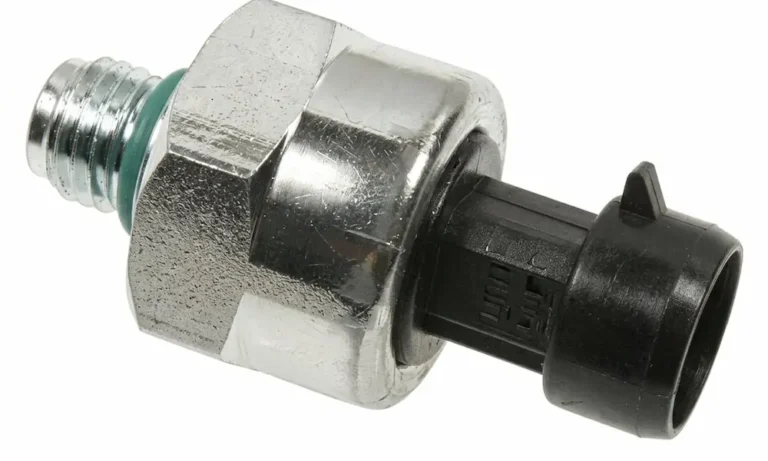
The Injection Control Pressure sensor acts as the eyes of your Powertrain Control Module (PCM). It measures hydraulic oil pressure inside the high-pressure oil rails and sends that data back as a live analog voltage signal.
Here’s why that matters: the 6.0 Powerstroke uses a Hydraulic Electronic Unit Injector (HEUI) system. Your injectors don’t run on fuel pressure alone — they need high-pressure engine oil to physically fire. Without accurate pressure data from the ICP sensor, the PCM can’t control fueling at all.
No signal. No fuel. No start.
How the High-Pressure Oil System Works
Before you touch a wrench, you need to understand what the sensor is measuring.
The Two-Stage Oil System
The 6.0 uses two separate oil circuits running in tandem. The low-pressure gerotor pump pulls oil from the pan, pushes it through the cooler and filter, and maintains roughly 50–70 PSI at idle. A portion of that oil feeds a holding reservoir beneath the oil cooler.
The high-pressure oil pump then takes that reservoir oil and slams it up to between 500 and 4,000+ PSI depending on engine load. That pressurized oil travels through standpipes into the cylinder head rails, where it waits above each injector.
How Injection Actually Happens
Inside each injector sits an intensifier piston. When the PCM commands a cylinder to fire, a solenoid opens, high-pressure oil rushes in, and slams down on the intensifier piston. Because the piston’s surface area is seven times larger than the fuel plunger below it, the pressure multiplies by a factor of seven. So 3,000 PSI of oil becomes 21,000 PSI of fuel spray at the nozzle.
The Closed-Loop Control System
The PCM manages this pressure through two components working together:
- The Injection Pressure Regulator (IPR) valve — bleeds off or holds excess pressure at the pump
- The ICP sensor — reports real-time pressure back to the PCM
If the sensor reports low pressure, the PCM closes the IPR to build more. If it reports too high, it opens the IPR to relieve it. The ICP sensor is the feedback signal that makes this entire loop work.
Early vs. Late Build: Find Your Sensor First
This is critical. The sensor location changes dramatically depending on your build year, and ordering the wrong part will strip threads or cause immediate failure.
| Engineering Generation | Model Years | Sensor Location | Pump Design | Oil Rail Design |
|---|---|---|---|---|
| Early Build | 2003 – Early 2004 | Rear engine valley, buried under turbocharger, mounted on pump cover | Aluminum swash-plate | Straight tubular rails with braided stainless hoses |
| Late Build | Late 2004 – 2007 | Front passenger side, visible through valve cover | Cast-iron V4 configuration | Wavy, high-capacity rails for pressure wave attenuation |
Quick visual check: If the sensor is buried under the turbo at the back of the engine, it’s an early build. If it’s sticking up clearly on the passenger front valve cover, it’s a late build.
The late-build redesign added 15 cubic inches of volume to the oil rails, which smoothed out hydraulic pulses during injection events. The sensor relocation alone transformed a 3-hour repair nightmare into a 30-minute job.
ICP Sensor Wiring: The Three-Wire Circuit
The sensor uses three wires to communicate with the PCM:
- 5-volt regulated reference — The PCM sends a steady 5V to power the sensor’s internal circuitry
- Signal return ground — A dedicated clean ground path back to the PCM’s internal ground plane
- Analog signal output — As oil pressure rises and compresses the internal diaphragm, voltage rises linearly from ~0.2V at zero pressure up through operating range
The Shared 5-Volt Reference Problem
Here’s where experienced techs earn their money. The PCM doesn’t generate a separate 5V reference for every sensor. It runs one internal regulator and splices that line to multiple sensors in parallel — including the manifold absolute pressure sensor, exhaust backpressure sensor, and coolant temperature sensor.
If the ICP sensor fails internally and shorts its reference wire to ground, it drags the entire shared reference circuit down. The PCM has a current-limiting resistor to prevent internal damage, but when that resistor absorbs the load, voltage can drop from 5V to nearly zero — taking all those other sensors offline simultaneously.
The result looks exactly like a dead PCM. It isn’t. It’s one shorted sensor killing the whole circuit.
Diagnostic tip: Use a clamp-on milliamp meter on individual reference wires at the computer connector. The wire pulling the most amperage points directly to the shorted sensor.
Symptoms of a Failing ICP Sensor
A bad ICP sensor produces very specific complaints. Know what you’re looking for.
- Crank, no start: The PCM won’t command the injectors to fire until it sees a minimum of 500 PSI — about 0.8V from the sensor. If the sensor reads low, the engine cranks endlessly even when mechanical pressure is fine
- Surging or loping idle: A fluctuating sensor signal causes the PCM to constantly chase pressure with the IPR valve, creating hydraulic spikes that translate directly to rpm swings
- Hot no-start: Engine oil thins as it heats up. A marginal high-pressure system or weak sensor that barely passes when cold will fail completely at operating temperature, then restart fine after the engine cools
Don’t confuse this with stiction. Stiction is when oxidized oil varnish gums up the injector spool valve itself — it causes misfires when cold that clear up as the engine warms. ICP issues get worse hot. Stiction gets better hot. Know the difference before spending money.
The Oil Wicking Problem: Why You Must Replace the Pigtail
This is the most overlooked part of any Ford 6.0 Powerstroke ICP sensor replacement, and skipping it guarantees a comeback.
The sensor has an internal diaphragm separating high-pressure oil from its electronics. After thousands of miles of thermal cycling and pressure spikes, that diaphragm cracks. Engine oil under thousands of PSI pushes directly into the electrical connector.
Through capillary action, that pressurized oil wicks up the inside of the copper wire insulation — sometimes traveling several feet from the original leak point. Engine oil is an excellent electrical insulator. As it coats the copper strands, it corrupts the analog voltage signal. In neglected cases, oil wicks all the way to the PCM or FICM connectors and ruins the computers entirely.
The rule: If the sensor leaked oil, cut the pigtail several inches back from the connector until you see shiny, dry copper. Install a fresh pigtail harness (5C3Z-12224-A) every single time.
Diagnostic Trouble Codes to Know
Don’t replace parts based on codes alone. Use them to guide your scan tool investigation.
| DTC | Definition | Common Cause |
|---|---|---|
| P2284 | ICP Sensor Circuit Range/Performance | Shorted harness or failed internal circuitry |
| P2285 | ICP Sensor Circuit Low | Short to ground, oil-soaked pigtail, or unplugged sensor |
| P2286 | ICP Sensor Circuit High | Short to battery voltage or failed internal resistor |
| P2287 | ICP Sensor Circuit Intermittent | Loose connection, broken wire, or chafed harness |
| P2290 | Injector Control Pressure Too Low | Sensor working but mechanical pressure is insufficient |
| P2291 | ICP Too Low – Engine Cranking | Can’t build 500 PSI to start; major mechanical leak or failed pump |
Live Scan Tool Data: What Numbers You Need
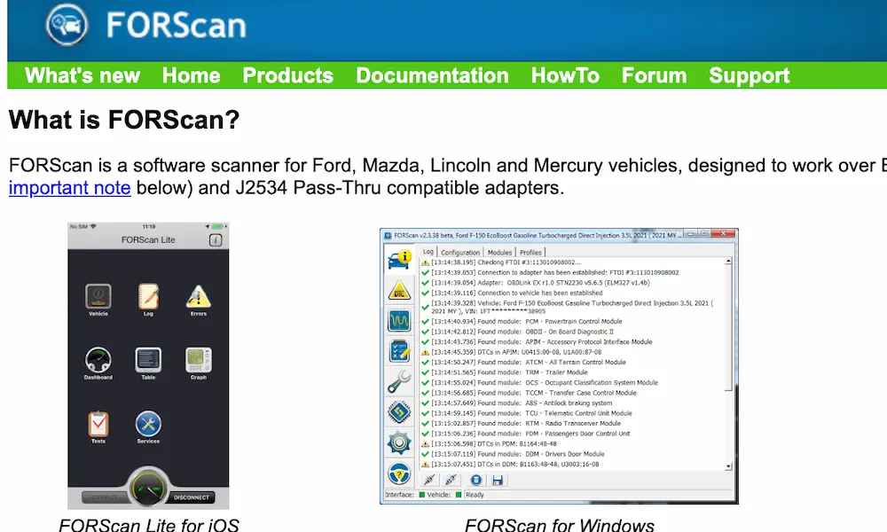
Connect a capable scan tool — FORScan, Ford IDS, or AutoEnginuity — and watch these parameters together.
| Parameter | Key On, Engine Off | Cranking Target | Hot Idle |
|---|---|---|---|
| ICP Sensor Voltage | 0.18 – 0.25V | Minimum 0.8V | 1.0 – 1.5V |
| System Pressure | 0 PSI | Minimum 500 PSI | 580 – 700 PSI |
| IPR Duty Cycle | 14% – 15% | Rises, stays below 85% | 22% – 30% |
| FICM Voltage | 48V | Minimum 45V | 48V |
Key On, Engine Off Baseline
With the key in the run position and the engine stationary, the sensor voltage must sit steadily between 0.18 and 0.25 volts. Reading 0.0V means an open circuit or missing 5V reference. Reading significantly above 0.3V means the internal resistor is already skewed — the sensor is feeding bad data before the engine even cranks.
The IPR duty cycle should rest at 14–15%, its default open position.
What to Watch During Cranking
As the starter spins the engine, watch for all of these simultaneously:
- Engine speed hits at least 120 RPM — a weak battery or tired starter won’t spin the pump fast enough to build pressure
- FICM voltage stays above 45V — the FICM needs 48 volts to snap injector spool valves open; low FICM voltage is a separate no-start cause entirely
- ICP voltage climbs past 0.8V — below this threshold, the PCM simply won’t fire the injectors
- IPR duty cycle climbs then holds below 85% — if it locks at 85% and pressure still won’t build, the PCM is commanding full pump output and still can’t get there. That’s a mechanical failure: a blown IPR seal, cracked standpipe, or failed high-pressure pump
The Unplug Test
Here’s a fast, powerful diagnostic move. If the engine won’t start and the ICP voltage reads low, simply unplug the sensor connector. The PCM detects an open circuit, throws a code, then switches to a default pressure strategy based on throttle position and RPM.
If the engine fires right up with the sensor unplugged, the mechanical system is fine. The sensor — or its wiring — is the sole problem. This single test saves hours of diagnostic time.
Ruling Out Mechanical Oil Leaks Before Replacing the Sensor
A P2291 code with low cranking pressure doesn’t automatically mean the sensor is bad. A cracked standpipe or blown dummy plug dumps oil directly back into the crankcase and mimics a failed sensor perfectly.
Air testing rules this out definitively. Remove the IPR valve from the high-pressure oil pump entirely and thread in a specialized pneumatic test fitting. This seals the drain path completely. Apply regulated shop air to pressurize the entire system up to the rails.
A healthy system holds 140 PSI silently for hours. Any audible hissing pinpoints your leak — at injector inlet seals, dummy plugs, standpipes, or the notorious snap-to-connect fitting on late-build pumps.
Don’t skip this test. Replacing a $60 sensor when a $15 o-ring is the real culprit is an expensive lesson.
NHTSA Safety Recall 05S34 and TSB 04-18-6
The ICP sensor wiring issues were severe enough to trigger federal intervention.
In June 2005, NHTSA Safety Recall 05V270 covered approximately 180,000 vehicles from the 2004 and 2005 model years. The defect report identified two specific failures causing stalls without warning: FICM harness chafing against mounting bolts from excess harness length, and improperly crimped terminal pins inside the ICP sensor connector itself.
Dealers were instructed to install protective loom kits or full replacement harnesses and replace the ICP sensor connector using high-tensile certified crimps.
Before that recall, Ford issued TSB 04-18-6 directing techs to perform a wiggle test on the engine harness while monitoring live sensor data. If manipulating the loom caused voltage dropout or engine stumble, harness repair was required before touching any electronics.
Check your VIN. If your truck falls in the affected range and the recall was never completed, a dealer must perform the repair at no charge.
Ford 6.0 Powerstroke ICP Sensor Replacement: Step-by-Step
Part Numbers and Component Selection
Aftermarket sensors fail fast. Their internal resistors drift with heat, feeding the PCM bad data that recreates the exact problem you just fixed. Use only OEM-quality parts.
| Component | Fitment | OEM Part Number |
|---|---|---|
| Early ICP Sensor | 2003 – Early 2004 | 3C3Z-9F838-EA |
| Late ICP Sensor | Late 2004 – 2007 | 4C3Z-9F838-A |
| Electrical Connector Pigtail | All Years (1994–2010) | 5C3Z-12224-A (WPT-1376) |
Early Build Replacement (2003–Early 2004)
Budget about three hours. The sensor is buried under the turbocharger at the rear of the block.
- Disconnect both negative battery cables to isolate the electrical system
- Remove air intake tubing, FICM, and FICM mounting bracket to clear the top of the engine
- Unbolt and fold the degas bottle to the passenger side — you don’t need to drain the cooling system if the hoses have enough slack
- Extract the heat shield covering the sensor using a low-profile flex-head ratchet
- Disconnect the pigtail using a 90-degree pick tool — the locking tab is brittle from heat cycling; don’t force it
- Extract the sensor using a specialized thin-wall 1-1/16″ crowfoot wrench — a standard deep-well socket won’t fit in the available clearance
- Thread in the new sensor and torque to 106 lb-in exactly
- Splice in the new pigtail using the Rotunda wire splice kit (164-R5903) with uninsulated metallic butt connectors and dual-wall adhesive-lined heat shrink tubing
Late Build Replacement (Late 2004–2007)
This is a 30-minute job thanks to the sensor relocation.
- Remove the alternator or right-side air intake ducting to access the front valve cover
- Disconnect the electrical connector — it’s fully accessible with no obstacles
- Place a standard 1-1/16″ deep-well socket directly on the sensor body
- Thread in the new sensor and torque to 106 lb-in
- Splice in the new pigtail using the same Rotunda crimp methodology
Critical Torque Specifications
| Component | Torque Spec |
|---|---|
| ICP Sensor | 106 lb-in |
| IPR Valve | 37 lb-ft |
| High-Pressure Oil Rail Plugs (M8) | 96 lb-in |
| HPOP Mounting Bolts | 18 lb-ft |
| Standpipes and Dummy Plugs | 60 lb-ft |
After reassembly, the engine will need extended cranking to purge trapped air from the rails before it fires. This is normal.
Keeping the System Healthy After Replacement
The 6.0 is notoriously sensitive to oil quality. As oil degrades, it loses its anti-foaming properties. Aerated oil compresses under pressure — and you can’t build injection pressure with compressible fluid.
- Shorten oil change intervals — don’t push this engine to factory change intervals with worn oil
- Use a quality 5W-40 full-synthetic diesel oil — especially in cold climates where rapid cold-start pressurization matters
- Keep fuel pressure above 60 PSI under load — fuel starvation destroys injectors regardless of how healthy the oil system is
- Monitor your FICM voltage regularly — a FICM dropping below 45V under load is a separate problem that mimics ICP failures on the scan tool