Staring at a mystery rear end under your GM and have no idea what you’re looking at? You’re in the right place. This guide walks you through every major GM rear axle — from the old drop-out third members to the bulletproof 14-bolt — using factory codes, physical measurements, and casting clues. Read to the end, because the difference between these axles can mean the difference between a reliable build and an expensive failure.
Why GM Rear End Identification Actually Matters
Here’s the problem: GM swapped axles across platforms constantly. A Chevelle might have left the factory with a 12-bolt, but the one sitting in a barn right now could have anything underneath it.
Relying on the build sheet alone is a mistake. Axles get swapped, housings get replaced, and stampings get ground off. Getting your GM rear end identification wrong means ordering the wrong parts, running the wrong gear ratio, or — worst case — grenading a 7.5-inch 10-bolt behind a 500-horsepower LS swap.
The right approach uses three layers of confirmation:
- Factory documentation (RPO codes)
- Physical tube stampings
- External housing measurements and casting features
Use all three. Never just one.
Start Here: RPO Codes and the Build Placard
The fastest starting point for GM rear end identification is the Regular Production Option (RPO) placard. GM affixed this sticker to every vehicle at the assembly plant, listing exact drivetrain specs in three-character alphanumeric codes.
Check these locations first:
- Inside the glove box
- Driver’s side door jamb (B-pillar)
- Under the trunk lid
On 2018 and newer vehicles, this information may also appear in a matrix barcode at the bottom of the driver’s door pillar.
For rear axle identification, RPO codes beginning with “G” tell you the gear ratio, axle type, and differential style. Some heavy-duty and fleet applications use “F” or “H” prefixes instead.
The code G80 is the one everyone knows — it means limited-slip, Positraction, or Gov-Lock, depending on the era.
Here’s a quick-reference table for the most common GM axle RPO codes:
| RPO Code | Description | Gear Ratio / Feature |
|---|---|---|
| G80 | Positraction / Limited Slip | Gov-Lock or Posi |
| G84 | Axle Rear | 4.10 |
| G87 | Ring Gear | 8.5-inch |
| G89 | Ring Gear | 7.5-inch |
| GU4 | Axle Rear | 3.08 |
| GU6 | Axle Rear | 3.42 |
| GT4 | Axle Rear | 3.73 |
| GT5 | Axle Rear | 4.10 |
| GV0 | Axle Rear | 3.55 |
| GU2 | Axle Rear | 2.73 |
The full RPO list runs deep — you can cross-reference the complete GM RPO code database at Sierra Gear if you need a specific code not shown here.
Reading the Axle Tube Stamping
When the axle isn’t in its original vehicle, the RPO placard is useless. That’s where the axle tube stamping takes over.
Look on the forward-facing side of the passenger-side axle tube, roughly three inches out from the center housing. That’s where GM stamped the ratio code, assembly plant, build date, work shift, and Positraction source.
GM used two distinct stamping formats — one before 1970 and one from 1971 onward.
Pre-1970 Stamping Format
Early codes use a two-letter ratio prefix, followed by a two-digit month, two-digit day, a plant letter, and an optional Positraction source letter.
Example: QY 01 01 G E decodes as:
- QY = gear ratio identifier
- 01 01 = January 1st
- G = Detroit Gear & Axle plant
- E = Eaton Positraction
Here’s a snapshot of early passenger car stamping codes covering a key production window:
| Code Prefix | Description | Notes |
|---|---|---|
| BA | 3.08 Open 10-Bolt | Standard Brakes (1965–1967) |
| BE | 3.08 Positraction 10-Bolt | Standard Brakes |
| BQ | 3.31 Open 12-Bolt | Standard Brakes (1966–1967) |
| BR | 3.07 Positraction 12-Bolt | Standard Brakes |
| BS | 3.31 Positraction 12-Bolt | Standard Brakes |
| FL | 3.55 Positraction 12-Bolt | Standard Brakes |
| FM | 3.73 Open Differential | Standard Brakes |
For a complete breakdown by year, the Nova Resource axle code page is one of the most thorough references available.
1971 and Later Stamping Format
Starting in 1971, GM switched to a Julian date system. The new format reads: ratio prefix → plant letter → three-digit Julian day → shift code → Positraction source.
Example: GW G 218 D E decodes as:
- GW = gear ratio code
- G = Detroit Gear & Axle
- 218 = the 218th day of the year
- D = Day shift
- E = Eaton Positraction
| Plant Letter | Location | Posi Source Code | Supplier |
|---|---|---|---|
| B | Buick | (blank) | No Positraction |
| C | Buffalo | D | Dana |
| G | Detroit Gear & Axle | E | Eaton |
| K | GM of Canada | W | Warner Motive |
| P | Pontiac | G | Detroit Gear & Axle |
| W | Warren, Michigan | O | Oldsmobile |
Casting Numbers and Housing Dates
The cast iron center section also has a molded casting date, usually near the five o’clock or seven o’clock position around the cover bolts. The format uses a letter for the month (A = January, B = February, etc.), followed by the day, then the last digit of the year.
C287 = March 28, 1967.
From the 1970s onward, GM shifted to a two-digit numerical month format instead of the letter system.
The 1955–1964 Drop-Out Third Member
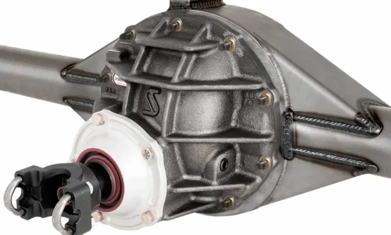
Before GM moved to integral housings, passenger cars and light trucks used a drop-out center section — essentially the same front-loading architecture as the legendary Ford nine-inch.
The entire gear assembly, carrier, and pinion unbolt from the front of the steel housing and pull straight out. This 8.2-inch drop-out design was standard on GM vehicles from 1955 to 1964. The 1955 and 1956 units typically carry casting numbers ending in 306.
It’s a great axle for period-correct restorations. For modern performance builds, skip it — aftermarket support is thin, and later integral housings handle torque far better.
GM 10-Bolt Axles: What You Need to Know
The 10-bolt is everywhere. It spans everything from fragile economy car axles to the genuinely strong 8.5-inch corporate unit. The “10-bolt” name refers to the ring gear fasteners — which conveniently matches the ten bolts on the inspection cover in most passenger applications.
Knowing exactly which 10-bolt you have determines whether your build lives or dies.
8.2-Inch Chevrolet 10-Bolt (1964–1972)
This axle showed up under Novas, first-gen Camaros, and Chevelles. It looks clean — the lower half of the cast iron housing is completely smooth, with no protrusions or casting bosses.
Cover: 11 inches in diameter, smooth. Some variants use a 10-5/8-inch cover with a diagonal hooded ridge across the top.
Key internal specs:
- Pinion shaft: 1.438 inches, 25 splines
- Axle shafts: 28 splines, C-clip retained
- Spider gear cross-pin bolt: requires a 1/2-inch wrench
That 1/2-inch cross-pin bolt is your instant identifier. It separates the 8.2-inch from every later 10-bolt immediately.
Power limits: Stock survival tops out around 400 hp on street tires. Drop to 350 hp with drag radials, and 300 hp with slicks. Even maxed-out aftermarket builds rarely hold past 500 hp.
8.2-Inch BOP 10-Bolt (1964–1972)
Buick, Oldsmobile, and Pontiac built their own completely separate 8.2-inch axle. The mounting brackets match the Chevy unit for line assembly compatibility — but nothing inside swaps between them.
Visual ID: The BOP cover has two reverse-scalloped indentations at the 3 o’clock and 9 o’clock positions. The housing also has horizontal reinforcement ribs on the sides — a single rib for Buick, double converging ribs for Pontiac.
Key difference: BOP axles use bolt-in axle shafts retained by four-bolt flange plates at the outer bearing — not C-clips. If the axle shaft breaks, the wheel stays on the car. That’s a genuine safety and performance advantage over the Chevy design.
Pinion: 1.438 inches, but 27 splines instead of the Chevy’s 25.
7.5-Inch and 7.625-Inch 10-Bolt (1975–2005)
This is the weak one. GM introduced it in 1975 to cut weight as emissions regulations squeezed engine output. It went under second and third-gen F-bodies, G-bodies, B-bodies, and light S-series trucks. In 1986, the ring gear grew slightly to 7.625 inches, but the housings and internals remain interchangeable.
Visual ID: Look at the bottom of the pumpkin. You’ll see two small, rounded cast protrusions at the five o’clock and seven o’clock positions — much smaller than what’s on the 8.5-inch. The oval cover measures 8-5/16 inches wide by 10-9/16 inches tall. The definitive measurement: the distance from the bottom center cover bolt to the adjacent bolt is exactly 3-1/4 inches.
Power limits: Stock ceiling sits around 350 hp on street tires. Even a maximum-effort rebuild rarely holds past 500 hp. The 1.438-inch pinion shaft deflects under load, the gear mesh shifts to the tooth edge, and the ring gear shears.
8.5-Inch and 8.6-Inch Corporate 10-Bolt (1970–Present)
This is the 10-bolt worth keeping. GM introduced it in 1970 as a corporate axle across all divisions except Cadillac. The 8.6-inch update arrived in 1999 for heavier modern trucks — same architecture, disc brakes instead of drums.
Visual ID: The housing features large, squared-off casting chunks hanging from the bottom at five and seven o’clock. These are noticeably bigger and flatter than the tiny 7.5-inch fangs. The front of the housing has flat casting webs extending outward on each side — exclusive to this variant. The round 11-inch cover has an asymmetrical bulge on the driver’s side for ring gear clearance. Bottom bolt spacing: 3-3/4 inches — a full half-inch more than the 7.5-inch.
Key internal specs:
- Pinion shaft: 1.625 inches — identical to the 12-bolt passenger car unit
- Pinion nut socket: 1-1/4 inch
- Ring gear bolts: 3/4-inch hex, 7/16-20 left-hand threads
- Spider gear cross-pin bolt: 5/16-inch wrench (not 1/2-inch like the 8.2-inch)
Power limits: With aftermarket 30-spline chromoly axles and a reinforced carrier, the 8.5-inch handles 1,000 hp reliably. It’s the axle the turbocharged Buick Grand Nationals used — cars that regularly wheel-hopped off the line. It’s a legitimate, economical alternative to a 12-bolt when budget matters.
GM 12-Bolt Rear Ends: The Gold Standard
The 12-bolt is the most coveted GM differential in performance circles. The name comes from the 12 ring gear bolts — which matches the 12 bolts on the inspection cover.
The critical rule: passenger car 12-bolt and truck 12-bolt share zero interchangeable parts. Not the pinion. Not the gears. Not the carrier. Nothing.
Passenger Car 12-Bolt (1964–1972)
Only eight years of production. That’s it. Original unmolested housings are genuinely scarce and command premium prices.
Cover ID: The oval cover measures 10-15/16 inches wide by 10-5/8 inches tall. Cast into the upper portion is an inverted V-shaped protrusion — that distinctive “conquistador helmet” ridge. It’s not decoration. It channels gear oil from the spinning ring gear directly onto the carrier bearings under hard acceleration.
Suspension variants — spot them instantly by the housing:
- Full-size (Impala): Four-link setup, no spring perches on the axle tubes
- A-Body/G-Body (Chevelle, Monte Carlo): Upper trailing arm eyelets cast into the top of the iron housing, angled outward
- F-Body/X-Body (Camaro, Nova): Flat saddle perches welded to the tubes for leaf springs
Key internal specs:
- Pinion shaft: 1.675 inches (listed as 1-5/8 inch in aftermarket catalogs)
- Factory Positraction: 30-spline C-clip axles, upgradeable to 35-spline for racing
- Power limit: approximately 600 hp in factory trim
- Drivetrain efficiency: 3% better than a Ford nine-inch due to reduced hypoid offset
Carrier breaks matter here. Three carrier sizes exist, and using the wrong one makes correct gear mesh physically impossible:
| Carrier Type | Gear Ratio Range | Common Application |
|---|---|---|
| Type 2 | 2.29 – 2.73 | Six-cylinder, low-output V8 |
| Type 3 | 2.76 – 3.73 | Mid-range performance |
| Type 4 | 3.90 – 6.14 | High-performance, drag racing |
Truck 12-Bolt (1963–1987)
The truck version ran through 1987 in C/K pickups, Blazers, and heavy vans. It’s not the same axle.
Cover ID: No inverted V ridge. The cover is roughly 10-7/8 inches square with a large asymmetrical bulge on one side only. Truck housings from 1963–1972 have a Panhard bar mount welded to the passenger-side tube. 1973 and later trucks switched to leaf springs — no Panhard mount.
Why it’s weaker: The pinion shaft drops to 1.438 inches — same as the weak 8.2-inch passenger axle. Early versions used 12-spline axles. Later versions moved to 17 splines. Aftermarket 30-spline conversion shafts fix the axle weakness, but the small pinion remains a permanent structural ceiling. Stock power limit: around 550 hp.
Don’t mix car and truck parts. The ring gear offsets and pinion dimensions are completely different. Attempting to cross parts between the two makes correct backlash impossible.
The 14-Bolt: GM’s Heavy-Duty Workhorse
The 14-bolt family covers three-quarter-ton and one-ton trucks that need real torque capacity. Two architectures exist — semi-float and full-float — and they’re not interchangeable.
9.5-Inch Semi-Float 14-Bolt
This lighter-duty 14-bolt targeted heavy half-ton and light 3/4-ton applications.
- Ring gear: 9.5 inches, 12 ring gear bolts internally
- Pinion shaft: 1.875 inches, 30 splines
- Axle retention: C-clips
- Axle shafts: 33 splines
- Wheel bolt pattern: six-lug or eight-lug depending on application
Visual ID: At the wheel end, the axle shaft terminates flush — no protruding hub cylinder sticking through the wheel center. Stronger than any 10-bolt, but less capable than the full-float design below.
10.5-Inch Full-Float Corporate 14-Bolt (1973–Present)
This is the one off-road builders chase. It’s considered one of the strongest light-truck differentials ever produced, and it genuinely rivals a Dana 70.
Full-float architecture: The wheels bolt to an external hub that rides on dual tapered roller bearings over a stationary spindle. The housing carries all vehicle weight — not the axle shafts. The 30-spline, 1.5-inch solid steel shafts only handle rotational torque. You can pull the axle shafts without lifting the truck or removing the wheels — a real advantage in the field.
Visual ID: A massive hub cylinder protrudes 2–4 inches through the wheel center, capped with a visible ring of heavy flange bolts. The cast cover is uniquely shield-shaped.
Key internal specs:
- Ring gear: 10.5 inches
- Pinion shaft: 1.750 inches, 30 splines
- Pinion support: straddle-mounted, with a bearing behind the gear teeth that virtually eliminates deflection under load
- The entire pinion support assembly removes from the front of the housing for easy gear setup
Width variants — GM managed three track widths by changing the hubs, not the housing length:
| Designation | Wheel-to-Wheel Width | Application |
|---|---|---|
| Cab & Chassis | 63.5 inches | Commercial flatbeds, narrow off-road builds |
| Single Rear Wheel | 67.5 inches | Standard 3/4-ton and 1-ton pickups |
| Van Width | 70.0 inches | G30/G35 commercial vans |
| Dual Rear Wheel | 72.0 inches | Dually 1-ton pickups |
The 63.5-inch Cab & Chassis variant is the off-road builder’s favorite — it achieves that narrow width by pairing the SRW housing with DRW-style hubs. Brakes were drum-only through 1998. Disc brakes arrived on select 1999 models and became standard by 2003.
Weight and strength comparison vs. Dana 60:
- Corporate 14-bolt: ~550 lbs, 1.5-inch spline diameter
- Dana 60: ~400 lbs, 1.3-inch spline diameter
- The 1.5-inch shaft delivers roughly 50% more torque capacity than the 1.3-inch Dana 60 shaft
11.5-Inch AAM 14-Bolt (2001–Present)
Starting in 2001, GM’s heaviest-duty Silverado and Sierra HD trucks got the American Axle & Manufacturing 11.5-inch unit. It shares the 14-bolt cover pattern but shares nothing internally with the 10.5-inch. Ring gear jumps to 11.5 inches, pinion goes to 2.0 inches. It exists purely for modern diesel torque loads — don’t try to cross-reference parts between this and the older corporate axle.
Why the Pinion Shaft Diameter Is the Real Story
Most people focus on ring gear size. That’s not where axles actually fail.
The real failure point on weak GM axles is pinion shaft deflection. When a small-diameter pinion twists under load, the gear mesh shifts from the thick center of the tooth to the fragile edge. The hardened steel shears, and the ring gear is done.
To calculate the actual torque your axle sees, multiply engine peak torque by the transmission’s first gear ratio, multiply by the rear axle ratio, then subtract 10% for driveline losses. That number is what the pinion shaft resists every hard launch.
GM solved this engineering problem not by making ring gears larger, but by upgrading pinion diameter:
- 1.438-inch pinion (7.5-inch, 8.2-inch, truck 12-bolt) → deflects under high torque, ring gear shears
- 1.625-inch pinion (8.5-inch corporate 10-bolt) → matches 12-bolt passenger car strength
- 1.675-inch pinion (passenger car 12-bolt) → 600+ hp in stock form
- 1.750-inch straddle-mounted pinion (14-bolt full-float) → effectively indestructible
For weaker axles, cast aluminum differential covers with load bolts press against the carrier bearing caps and resist deflection under load — artificially raising the survival threshold of 8.2-inch and 8.5-inch housings without a full housing swap.
Quick Visual ID Cheat Sheet
When you’re under the car without any documentation, these physical measurements give you a definitive answer fast:
| Axle | Ring Gear | Bottom Cover Bolt Spacing | Key Visual Marker |
|---|---|---|---|
| 8.2-inch Chevy 10-bolt | 8.2 in | — | Smooth lower housing, no protrusions |
| 8.2-inch BOP 10-bolt | 8.2 in | — | Scalloped cover, horizontal housing ribs |
| 7.5/7.625-inch 10-bolt | 7.5–7.625 in | 3-1/4 inches | Small rounded fangs at bottom |
| 8.5/8.6-inch 10-bolt | 8.5–8.6 in | 3-3/4 inches | Large squared-off casting chunks, front webs |
| Car 12-bolt | 8.875 in | — | Oval cover with inverted V ridge |
| Truck 12-bolt | 8.875 in | — | Square cover, asymmetrical bulge, no V ridge |
| Semi-float 14-bolt | 9.5 in | — | Flush axle end, no protruding hub |
| Full-float 14-bolt | 10.5 in | — | Hub cylinder through wheel center |
| AAM 14-bolt | 11.5 in | — | Modern HD trucks, 2001+ |
That bolt spacing measurement — 3-1/4 vs. 3-3/4 inches — is the fastest way to tell a 7.5-inch from an 8.5-inch without any tools other than a tape measure. Use it every time.
Never trust a single identification method. Layer the RPO code, the tube stamping, and the physical measurements together — and you’ll know exactly what you’re working with before you spend a dollar on parts.