Your car’s surging, stalling, or shifting like it’s having a bad day — and a misadjusted throttle position sensor might be the culprit. This guide walks you through exactly how to adjust throttle position sensor step by step, covering everything from electrical testing to vehicle-specific procedures. Stick around — the relearn section at the end is one most people skip, and it’s where everything falls apart.
What Does a Throttle Position Sensor Actually Do?
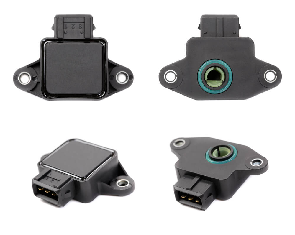
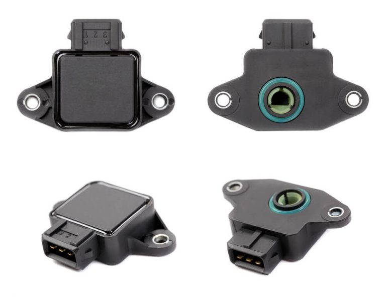
The throttle position sensor (TPS) sits on your throttle body and tracks exactly how far open the throttle plate is. It converts that mechanical angle into a voltage signal and feeds it to your engine control unit (ECU) in real time.
Your ECU uses that data to calculate:
- How much fuel to inject
- When to fire the ignition
- When your automatic transmission should shift
- How hard to clamp the transmission’s clutch packs
Modern drive-by-wire systems use dual opposing sensors for redundancy. One climbs from 0.5V to 4.5V as you open the throttle. The other drops from 4.5V to 0.5V simultaneously. The ECU adds them together — if the sum isn’t 5V, it kills the electronic throttle and throws the car into limp mode.
That’s how critical this sensor is.
Signs Your TPS Needs Adjustment or Replacement
Don’t guess — look for these specific symptoms before you start turning screws.
| Symptom Category | What You’ll Notice | Why It Happens |
|---|---|---|
| Idle Problems | Hunting, surging, stalling on decel | ECU can’t confirm throttle is closed, disrupting idle air control |
| Acceleration Issues | Hesitation, bucking, flat spots | Worn potentiometer track causes voltage dropouts mid-sweep |
| Transmission Behavior | Harsh shifts, slipping, no downshift | Wrong load data reaches the transmission module, killing line pressure |
| Warning Lights | Check engine light, limp mode | ECU logs codes like P0121, P0122, P0123 when voltage falls out of range |
If your transmission is slipping alongside poor engine response, automatic transmissions rely entirely on TPS data to set hydraulic line pressure. A bad reading means slipping clutch packs — and that gets expensive fast.
How to Test Your TPS Before Adjusting Anything
Adjusting a broken sensor wastes your time. Test first.
Step 1: Visual Inspection
Check the sensor housing and wiring harness for:
- Green oxidation or corrosion on the connector terminals
- Frayed, burnt, or pinched wire insulation
- Cracked sensor housing from heat or vibration
The TPS sits right on the throttle body, exposed to heat cycles and engine vibration constantly. Moisture is the most common killer, and it usually shows up as green corrosion on the connector pins.
Step 2: Electrical Testing With a Multimeter
You need a high-impedance digital multimeter. Turn the ignition to the ON position — engine off.
Critical safety tip: Don’t pierce the wire insulation with your multimeter probes. That permanently breaks the waterproof seal, letting moisture wick down the wire over time. Use back-probing T-pins that slide past the rubber seals at the connector’s rear without damaging anything.
Run these three checks in order:
1. Reference Voltage
Connect your black lead to a solid engine ground. Back-probe the reference wire with your red lead. You should read a stable 5.0 volts. Anything less points to a wiring fault or ECU issue.
2. Ground Integrity
Move the red lead to the ground circuit terminal. You want near-zero resistance back to the battery negative. A bad ground makes the sensor voltage float — which looks exactly like a failing sensor.
3. Signal Sweep Test
Back-probe the signal wire with your red lead. Slowly sweep the throttle by hand from fully closed to wide open. Watch the voltage climb smoothly from roughly 0.5V to 4.5V.
Any sudden drops, dead spots, or erratic spikes during that sweep mean the internal resistive track is destroyed. Per A-Premium’s P0122 diagnostic guide, a failed sweep test means you need a new sensor — adjustment won’t fix physical track damage.
If you have access to an oscilloscope, use it. Scopes reveal micro-second voltage dropouts that a multimeter simply can’t catch.
How to Adjust Throttle Position Sensor: Vehicle-Specific Methods
If your sensor passes the sweep test but the baseline voltage is wrong, mechanical adjustment is the fix. Most legacy sensors have slotted mounting holes — loosen the screws slightly and rotate the sensor body to shift the baseline voltage.
Here’s how it works across the most common platforms.
Ford Mustang (Fox Body and SN95, 1986–2004)
These are some of the most straightforward TPS adjustments you’ll find. LMR.com’s TPS adjustment guide walks through the full procedure.
What you need: Digital multimeter, Phillips head screwdriver
Steps:
- Turn ignition ON, engine OFF
- Back-probe the green signal wire with your positive multimeter lead
- Ground the negative lead to the engine block
- Loosen the two TPS mounting screws just enough to rotate the sensor
- Twist the sensor body until voltage reads between 0.75V and 0.98V
- Tighten the screws and recheck the voltage — sensors can shift slightly when you torque the hardware down
That sub-1V baseline tells the ECU the throttle is fully closed. Getting it right prevents the erratic idling and stalling these engines are notorious for when the TPS is off.
Toyota 22RE, 3VZ, and 4AGE Engines
Toyota’s approach is completely different — and honestly more complex. These sensors contain an internal idle switch that must physically open and close at precise throttle angles. Voltage targets alone won’t cut it here.
Before anything else, clean the throttle body thoroughly. Carbon buildup stops the butterfly valve from seating fully against its stop, and your entire adjustment will be wrong from the start.
The feeler gauge method:
You’re testing electrical continuity across specific sensor terminals while inserting feeler gauges between the throttle linkage and the stop screw. Use small alligator clip jumper wires to hold your multimeter leads on the sensor pins while you work.
| Feeler Gauge Thickness | Required Reading (Idle to Ground) | What It Means |
|---|---|---|
| Zero (throttle fully closed) | Full continuity (low ohms) | ECU runs idle air control and baseline ignition |
| ~0.50mm (minimum spec) | Full continuity (low ohms) | Accommodates cable stretch without killing idle mode |
| ~0.85mm (maximum spec) | Open circuit (infinite ohms) | ECU switches to main acceleration fuel mapping |
According to Toymods Car Club’s TPS adjustment thread, getting this switch threshold wrong causes severe engine bucking at low speeds. The ECU rapidly toggles between idle and acceleration fuel maps — which feels exactly as rough as it sounds.
After setting the idle switch, check the variable track resistance from idle to wide-open throttle. It should sweep smoothly between roughly 3kΩ and 10kΩ depending on your specific engine variant.
Jeep Cherokee and Comanche — Renix Systems
Early Renix-equipped Jeeps with automatic transmissions use a dual-sided TPS — one potentiometer for the ECU, one for the transmission control module (TCM).
The Renix system doesn’t use fixed voltage targets. It works on percentages of the reference voltage, which varies slightly with your electrical system’s health.
Engine side (3-wire flat connector):
Back-probe the reference wire and record the exact voltage. Adjust the sensor until the signal output equals 17% of that reference voltage.
Transmission side (4-wire square connector):
Record the reference voltage on this separate connector. With the sensor at the same physical position, the transmission signal must equal 83% of its reference voltage.
Here’s the catch: rotating the sensor housing moves both potentiometers simultaneously. If worn internal tracks prevent you from hitting both the 17% and 83% targets at the same mounting angle, the sensor is done. Replace it.
Manual transmission models can ignore the square connector entirely — much simpler.
BMW and MV Agusta Motorcycles
Multi-cylinder motorcycle applications add another layer of complexity. BMW boxer twins and MV Agusta models run independent throttle bodies per cylinder, and they must be perfectly synchronized.
BMW Bosch systems:
Back off the mechanical stop screw until the throttle plate binds against the bore. Rotate the sensor until the multimeter reads exactly 250 millivolts — this sets absolute zero. Then turn the stop screw back in until the voltage climbs to approximately 370 millivolts, setting the physical resting angle.
After locking the sensor, start the engine and use vacuum manometers to match airflow between both throttle bodies. Any baseline error creates asymmetric fueling, which causes vibration and poor low-speed behavior.
MV Agusta Weber Marelli systems:
These use non-linear sensor tracks — meaning any closed-position error gets amplified progressively as you open the throttle. On specific models, the target baseline is 308 millivolts. Get this wrong and the fueling curve is skewed across the entire rev range.
If the sensor has moisture contamination, it can sometimes be rebuilt. Open the housing by pressing out the steel pins, clean the carbon tracks and brush spindles with pure alcohol, dry thoroughly with cotton swabs, and reassemble with fresh rubber seals.
Aftermarket EFI Systems: Holley Sniper and US Shift
Aftermarket standalone systems interact with the TPS in ways factory setups don’t.
Idle air control interaction:
Holley’s idle tuning guide explains this clearly: adjusting the mechanical idle screw can raise TPS voltage above its calibrated zero. The ECU sees that as an accelerator input and immediately exits idle control mode — freezing the IAC valve. If this happens, you need to perform a software TPS reset through the Holley handheld or laptop interface before continuing idle tuning.
Transmission line pressure failsafe:
US Shift’s TPS instructions specify a minimum resting voltage of 0.35V — never zero. Here’s why: if the linkage breaks or the harness disconnects completely, voltage drops to true zero. The controller reads that as an impossible value, triggers maximum line pressure, and locks shifts into a limp-home map. That protects the transmission until you can repair the fault.
Torque Specs: Don’t Skip This Step
Mounting screws on a TPS are tiny, but they matter. Under-torque them and the sensor vibrates out of adjustment. Over-torque them and you crack the plastic housing or strip the throttle body threads.
Torque values for small sensor hardware are measured in inch-pounds, not foot-pounds. For Holley aftermarket sensors, that’s 18 inch-pounds with thread-locking compound. Heavy-duty commercial applications like Allison transmissions run between 84 and 120 inch-pounds.
One more thing: if you’re using an extension adapter on your torque wrench, you must set the wrench lower than the target torque value. The extension increases the tool’s effective length, which amplifies leverage and overtightens the fastener even when the wrench clicks at the “correct” setting.
How to Reset the Throttle Position Sensor After Adjustment
This is the step most people skip — and it’s why their idle is still rough after a perfect adjustment.
Your ECU builds adaptive memory over time, compensating for wear and carbon buildup. After you adjust the TPS, that old memory fights against your new calibration. You need to clear it.
Battery Disconnect Method
Disconnect the negative battery terminal and wait 10–20 minutes. For faster results, press the brake pedal while disconnected — it drains residual capacitance through the brake light circuit.
After reconnecting, start the engine without touching the accelerator and let it idle with no accessory loads for several minutes. The ECU remaps the new baseline.
Passive Key Cycle Method (Hyundai and Similar)
Some manufacturers use ignition-cycle sequences instead of battery disconnects. Per a Reddit thread solving the Hyundai relearn procedure:
- Turn the key to ON — don’t start the engine
- Wait 15 seconds while the throttle body sweeps to map its endpoints
- Turn the key fully OFF
- Repeat this cycle five times consecutively
The ECU passively locks in the new voltage limits without any tools required.
Active Pedal Pulse Method
For older electronic throttle control setups, DiGi Electronics describes an active calibration method:
- Turn ignition ON
- Rapidly press the accelerator to the floor and release it several times within 5 seconds
- Hold the pedal to the floor for 20 seconds until the check engine light flashes
- The ECU records the new minimum and maximum voltage thresholds
Scan Tool Calibration
Modern vehicles are moving away from manual relearn procedures entirely. The system automatically sweeps the throttle, records the voltage endpoints, and writes them to non-volatile memory — no key cycle timing, no guesswork.
Getting the Adjustment Right the First Time
Learning how to adjust throttle position sensor properly isn’t just about hitting a voltage number. It’s about understanding that every number you set cascades through the entire powertrain — from idle stability to fuel economy to whether your transmission clutch packs survive another 100,000 miles.
Test before you adjust. Use back-probing pins, not pierced wires. Hit the correct baseline for your specific platform. Torque the hardware properly. And always — always — run the relearn procedure when you’re done.
Do those five things and your engine will respond exactly the way it should.