Is your Toyota pickup bucking, surging, or refusing to idle right? A bad 22RE throttle position sensor adjustment might be your culprit. This guide walks you through everything — from understanding how the sensor works to nailing the calibration. Stick around to the end, because one wrong step here can break your timing setup entirely.
What Does the 22RE Throttle Position Sensor Actually Do?
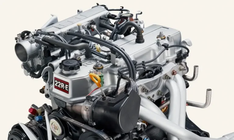
The throttle position sensor (TPS) sits on the side of your throttle body. It tells the engine control unit (ECU) exactly what the throttle plate is doing at any given moment.
It handles three jobs simultaneously:
- Reads throttle angle using an internal resistive track
- Detects true idle through a dedicated contact switch
- Reports acceleration rate so the ECU can calculate fuel delivery
When the sensor is calibrated correctly, the ECU can nail injector pulse width, ignition timing, and transmission shift points all at once. When it’s off, everything downstream suffers.
Understanding the 4-Pin Connector Pinout
The TPS uses a four-wire interface. Early models (pre-1989) used a round connector. Later models switched to a square design in 1989. The pinout stayed the same throughout the production run.
| Terminal | Function | What It Does |
|---|---|---|
| VC | Reference Voltage | Receives a steady 5V feed from the ECU |
| VTA | Variable Throttle Angle | Outputs analog voltage based on throttle position |
| E2 | Dedicated Ground | Returns signal directly to ECU, not chassis ground |
| IDL | Idle Switch | Closes the circuit between IDL and E2 at full throttle close |
The IDL terminal is critical. The ECU uses the closed idle circuit to enable base timing diagnostic mode — something most people don’t realize until their timing procedure fails completely.
What Goes Wrong When the TPS Is Out of Adjustment
A slightly misaligned TPS doesn’t just cause rough idling. It triggers a cascade of problems across the entire engine management system.
You Can’t Set Base Ignition Timing
This is the big one. To lock base timing, you jump the TE1 and E1 terminals in the diagnostic port. The ECU will only honor that command if the idle switch is closed simultaneously.
If the TPS is misadjusted and the idle contacts stay open, jumping those terminals does nothing. Your timing mark stays floating around 12 degrees BTDC instead of dropping to the base 5 degrees. Mechanics who don’t know this connection exists rotate the distributor to force the mark down manually — then wonder why the engine runs terribly after the jumper wire is removed.
Hesitation and Bucking at Highway Speed
Internal carbon track wear creates dead spots on the resistive sweep. When the wiper arm crosses one, resistance spikes to infinity. The ECU reads it as “foot off the pedal” and cuts fuel instantly. A fraction of a second later, fuel slams back in. The result is rhythmic bucking at a steady cruise speed — commonly misdiagnosed as bad plug wires or a failing fuel pump.
Transmission Shift Problems
The A340 automatic transmission control module reads the VTA signal to calculate engine load and shift timing. A bad TPS causes harsh shifts, early upshifts, or the transmission holding gears too long. There’s also a physical throttle valve cable running from the linkage to the transmission housing. Factory spec says the gap between the cable stopper and rubber boot should measure no more than 1mm at rest. Too tight or too loose means premature clutch pack wear.
Before You Touch the Sensor — Do These First
Adjusting the TPS while mechanical problems exist underneath it is pointless. You’ll calibrate to a broken baseline.
Clean the Throttle Body
The PCV and EGR systems dump oil vapor and exhaust byproducts straight into the intake. Over time, that material hardens into a tar-like crust inside the throttle bore and around the butterfly valve edges. This buildup can hold the throttle plate open by a fraction of a millimeter — enough to throw off the entire idle calibration. Scrub the bore clean with solvent and a soft brush before proceeding.
Set the Throttle Stop Screw First
This step is misunderstood constantly. The throttle stop screw does not set idle speed. Idle speed comes from the idle air bypass screw and the idle air control valve. The stop screw exists solely to prevent the butterfly valve from jamming against the aluminum bore under vacuum.
Here’s how to set it correctly:
- Loosen the jam nut
- Back the screw out until there’s visible daylight between the screw tip and the throttle linkage lever
- Turn the screw in slowly until it just makes contact
- Advance it exactly one additional quarter turn
- Hold the screw in position and tighten the jam nut firmly
That quarter turn lifts the butterfly off the bore wall just enough to prevent binding. This position becomes your mechanical zero point. Everything else calibrates relative to it.
Check the Dashpot
The dashpot cushions the throttle linkage as it snaps shut. If the plunger is adjusted too far into the linkage path, its spring force can overpower the throttle return spring — keeping the throttle from ever fully reaching the stop screw. That means the idle switch never closes. Calibration becomes impossible. Make sure the plunger makes first contact roughly halfway through the throttle’s return stroke from wide-open.
Upgrade the Mounting Hardware Before You Start
The TPS mounts with two Japanese Industrial Standard screws. They look like Phillips head, but they’re not. Using a standard Phillips driver strips them immediately, especially after decades of galvanic corrosion against aluminum.
Swap them out for 3mm metric Allen head cap screws. A ball-end hex wrench can engage the bolt at extreme angles, which makes future adjustments possible while the throttle body stays on the engine. It’s a 10-minute change that saves hours of frustration later.
Also worth noting: the lower mounting screw has terrible access when the throttle body is installed because the coolant neck blocks the angle. Doing the initial calibration with the throttle body on a clean workbench makes life much easier.
The Step-by-Step 22RE Throttle Position Sensor Adjustment
You need three things before starting:
- Digital multimeter capable of reading 0 to 10,000+ ohms
- Precision feeler gauges in the specific metric thicknesses listed below
- Alligator clip test leads — the terminal pins are too tightly spaced for manual probes
Step 1 — Mount the Sensor Loosely
Seat the TPS onto the throttle shaft. Make sure the internal engagement tabs align with the flat faces of the shaft. Install the Allen bolts snug enough to hold the sensor but loose enough to rotate it by hand with light resistance.
Step 2 — Confirm Baseline Continuity
Clip your multimeter leads to the IDL and E2 terminals. With no feeler gauge inserted and the throttle fully closed against the stop screw, rotate the sensor housing fully clockwise. The meter should show near-zero resistance — full continuity.
Step 3 — Find the Transition Point
This is the most critical step. Insert the Idle Circuit Open Threshold feeler gauge (from the spec tables below) between the stop screw tip and the throttle linkage lever. Do not insert it between the butterfly valve and the bore — that’s a common mistake that ruins the calibration entirely.
With your multimeter still on IDL and E2, slowly rotate the sensor housing counter-clockwise. The exact moment the meter jumps from low resistance to open loop — stop. Lock the Allen bolts down immediately, holding the housing steady while you tighten.
Step 4 — Verify Both Threshold Points
Remove the thicker gauge. Insert the Idle Circuit Closed Threshold gauge (thinner). The meter must immediately return to continuity (low resistance). If the switch stays open with the thinner gauge in, your adjustment is too sensitive. Loosen and repeat.
Step 5 — Sweep the VTA Signal
Move your leads to VTA and E2. Slowly sweep the throttle from fully closed to wide open and back. Resistance must climb and fall in a perfectly smooth, linear arc. Any spike, dropout, or freeze during the sweep means the internal carbon track is worn and the sensor needs replacement — no amount of adjustment fixes a dead spot.
Calibration Spec Tables
Use these exact values based on your engine’s production year.
1985–1988 Models
| Test Condition | Feeler Gauge | Terminals | Target Resistance |
|---|---|---|---|
| Throttle fully closed | 0.00mm | VTA – E2 | 200–800 ohms |
| Idle circuit closed | 0.57mm (0.0224″) | IDL – E2 | Under 2,300 ohms |
| Idle circuit open | 0.85mm (0.0335″) | IDL – E2 | Open / Infinite |
| Wide open throttle | None | VTA – E2 | 3,300–10,000 ohms |
| Reference circuit | Any position | VC – E2 | 3,000–7,000 ohms |
1989–1995 Models
| Test Condition | Feeler Gauge | Terminals | Target Resistance |
|---|---|---|---|
| Throttle fully closed | 0.00mm | VTA – E2 | 470–6,100 ohms |
| Idle circuit closed | 0.50mm (0.0197″) | IDL – E2 | Under 2,300 ohms |
| Idle circuit open | 0.77mm (0.0303″) | IDL – E2 | Open / Infinite |
| Wide open throttle | None | VTA – E2 | 3,100–12,100 ohms |
| Reference circuit | Any position | VC – E2 | 3,900–9,000 ohms |
If your sensor transitions slightly outside these exact thicknesses, that doesn’t automatically mean it’s failed. Accumulated manufacturing tolerances between the throttle body casting, the butterfly valve wear, and the sensor shaft are normal. As long as there’s a clean, repeatable transition and a smooth VTA sweep, the sensor is good.
Choosing a Replacement TPS (If You Need One)
Toyota discontinued several original part numbers. The replacements ending in 28010, 28030, and 20060 have been superseded by the part ending in 20050. Always match the last five digits stamped on your original sensor to confirm the internal resistance sweep matches your ECU’s calibration.
The market is full of counterfeits that look identical to genuine Denso units. Low-quality aftermarket sensors often fail the calibration test straight out of the box because their internal tolerances cause the idle transition point to fall completely outside the feeler gauge window. Always bench-test any replacement before installing it on the engine.
Setting Base Timing After Calibration
Reinstall the throttle body, reconnect all coolant hoses and vacuum lines, and bring the engine to full operating temperature.
Locate your diagnostic port. On pre-1987 models, it’s a round green two-pin connector near the air cleaner. On 1987 and later models, look for a rectangular multi-pin box near the main fuse block.
Bridge the TE1 and E1 terminals with a jumper wire. Because your TPS is now correctly calibrated, the ECU will detect the closed idle switch, disable its dynamic timing advance, and lock timing at a static 5 degrees BTDC.
Point your timing light at the crankshaft pulley. Loosen the distributor hold-down bolt and rotate the housing until the white timing mark aligns with the 5-degree mark on the oil pump tab. When you remove the jumper wire, the timing mark will float forward to approximately 12 degrees BTDC under active ECU control. That movement confirms the TPS and ignition management system are communicating correctly.
Clearing Diagnostic Trouble Codes
If your TPS was failing or you unplugged it with the ignition on, the ECU has stored fault codes. The two most relevant ones are:
- Code 41 — Open or short circuit in the VTA signal path. Triggers if voltage stays below 0.2V or above 4.8V for more than half a second
- Code 51 — Idle switch condition fault. Triggers when the ECU expects a closed idle signal and doesn’t find one
Disconnect the negative battery terminal for several minutes to wipe the ECU memory clean. Reconnect, then run the engine through varied conditions — hard acceleration, steady cruise, long deceleration, stable idle. A clean bill of health means no returning check engine light.
If the TPS Checks Out But Problems Persist
Sometimes the TPS passes every test but the truck still runs rough. Don’t stop there.
Air Flow Meter issues often mimic TPS symptoms. If the internal vane sweep is erratic or the idle mixture screw is tampered, the AFM output won’t match the throttle angle data and the ECU gets confused. A baseline reset of 2.5 turns counter-clockwise from fully seated is a solid starting point on a heavily adjusted meter.
EGR valve sticking open pushes inert exhaust gas into the intake at idle. It creates a massive lean condition that feels exactly like a worn carbon track inside the TPS — surging, hesitation, and light-throttle misfire. Temporarily blocking the EGR pipe where it meets the intake manifold is a fast diagnostic test to isolate the problem.
Cold-start issues that look like fuel delivery failures often come from the thermo-time switch. When cold, it should measure 20–40 ohms (brown square connector) or 30–50 ohms (black round connector). If resistance runs over 60 ohms, the cold-start injector never fires and the engine cranks endlessly on cold mornings regardless of where your TPS is adjusted.