Misplace one check ball during your 4L60E rebuild and you’ll be pulling the transmission back out within days. These tiny spheres control everything from shift feel to clutch survival. This guide covers every check ball location, what each one does, why they fail, and how to fix it. Read to the end — the material science section alone could save your transmission.
What Are Check Balls and Why Do They Matter?
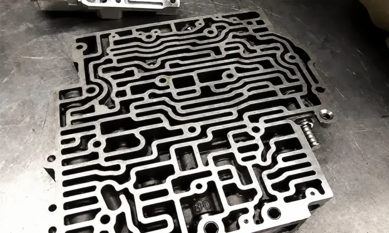
Check balls are small spherical valves inside your 4L60E’s valve body and transmission case. They act as one-way hydraulic gates — seating against an orifice to slow fluid flow or rolling away to allow a fast exhaust.
This simple action controls:
- How quickly clutch packs apply
- How fast they release during downshifts
- Whether your shifts feel smooth or brutally harsh
The 4L60E uses 11 check balls total. Eight are loose spheres you manually place during assembly. Three are permanently encapsulated in metal housings pressed into the case and input shaft.
Miss even one, and you’re looking at slipping gears, burned clutches, or violent engagements.
4L60E Check Ball Locations: The Full Map
The ATSG manual — the industry bible for transmission rebuilding — assigns specific numbers to each check ball. Here’s where every single one lives.
Lower Valve Body (7 loose balls):
- Numbers 2, 3, 4, 5, 6, 8, and 12
Transmission Case (1 loose ball + 3 encapsulated):
- Number 1 (loose, near the 3-4 accumulator)
- Numbers 7, 9, and 10 (encapsulated, press-fit into the case)
Input Shaft Tip:
- One encapsulated ball for torque converter clutch control
When you remove the valve body, tilt it and those seven loose balls will fall right out. Keep that in mind before you flip it over a workbench.
| ATSG Number | Location | Type | Function |
|---|---|---|---|
| 1 | Transmission Case | Loose | 4th gear accumulator feed/exhaust |
| 2 | Lower Valve Body | Loose | 3rd clutch accumulator feed |
| 3 | Lower Valve Body | Loose | Reverse input clutch control |
| 4 | Lower Valve Body | Loose | 3-4 clutch exhaust shuttle |
| 5 | Lower Valve Body | Loose | Overrun clutch feed control |
| 6 | Lower Valve Body | Loose | Overrun clutch logic control |
| 7 | Transmission Case | Encapsulated | 3rd accumulator/exhaust capsule |
| 8 | Lower Valve Body | Loose | 1-2 upshift / 2-4 band application |
| 9 | Transmission Case | Encapsulated | Lo/Detent reverse ball capsule |
| 10 | Transmission Case | Encapsulated | Low/Reverse clutch quick exhaust |
| 12 | Lower Valve Body | Loose | Forward clutch accumulator |
| Input Shaft | Input Shaft Tip | Encapsulated | Torque converter clutch lockup |
What Each Valve Body Check Ball Actually Does
Check Ball #2 — The 2-3 Shift Cushion
During a 2-3 upshift, the #2 ball seats against the separator plate. This forces fluid through a restricted orifice, slowing the pressure buildup in the third gear accumulator. The result? A smooth, cushioned engagement into third gear.
On a 3-2 downshift, the flow reverses. The ball rolls away from its seat and fluid exhausts fast — preventing a momentary bind where both second and third gear are fighting each other.
Check Ball #3 — Reverse Input Clutch Control
This ball is entirely dedicated to reverse operation. When you move the selector to Reverse, pressurized fluid slams the #3 ball against its seat and forces fluid through orifice #17. This controls how fast the reverse input clutch applies at idle.
Without it working correctly, you get a violent clunk shifting into Reverse — the kind that snaps drivetrain mounts over time.
Check Ball #4 — 3-4 Clutch Shuttle
The #4 ball directs fluid during upshifts and controls exhaust during downshifts in the 3-4 circuit. This one matters enormously because the 4L60E’s 3-4 clutch pack is the most common failure point in the entire transmission.
If the #4 ball doesn’t seal properly, pressurized 3-4 fluid bleeds into exhaust passages. The clutch loses clamping force, starts slipping under load, generates heat, and burns up. You’ll see a gear ratio error code, and you’ll be rebuilding the transmission again.
Check Ball #5 and #6 — Overrun Clutch Team
These two work together to control the overrun clutch — the holding member that provides engine braking in manual gear ranges. Ball #5 controls feed rate; ball #6 acts as a logic shuttle to determine whether fluid comes from the manual valve or the automatic shift circuits.
Performance builders pay close attention to these. They’re commonly modified or deleted in heavy-duty applications, and GM has issued technical service bulletins addressing premature wear in these circuits.
Check Ball #8 — 2-4 Band Application
When the PCM commands a 1-2 shift, fluid heads toward the 2-4 servo. Ball #8 seats and forces that fluid through a restriction, controlling how fast the servo pin extends and how smoothly the 2-4 band wraps around the reverse input drum.
During a 3-2 downshift, the ball unseats completely and fluid bypasses the restriction entirely — delivering immediate band application for engine braking.
Check Ball #12 — Forward Clutch Accumulator
Every time you shift from Park or Neutral into Drive, #12 goes to work. It seats under the initial pressure wave and forces fluid through a calibrated orifice, cushioning the forward clutch engagement.
Leave this ball out during a rebuild and the vehicle clunks violently into Drive every single time. That clunk isn’t just annoying — it’s destroying your clutch pack with every engagement.
Case-Side Check Balls: Don’t Forget These
Check Ball #1 — Fourth Gear Accumulator
This loose ball sits on the case side of the separator plate near the 3-4 accumulator. It cushions the 2-4 band apply during the 3-4 overdrive shift, then opens wide for fast exhaust when you downshift out of fourth.
This ball falls out of the case constantly when technicians remove the separator plate. Check the floor before you walk away from the transmission.
Encapsulated Check Balls #7, #9, and #10
These three live in press-fit metal capsules deep in the transmission case. You can’t reposition them by hand — you need a slide hammer and threaded adapter to remove them without trashing the aluminum bore.
The #9 and #10 capsules manage the low and reverse clutch circuits using a double orifice design. This design allows controlled application and near-instant exhaust of the low/reverse clutch in Park, Reverse, and Manual Low.
Input Shaft Check Ball — Torque Converter Lockup
Pressed into the very tip of the input shaft, this encapsulated ball controls torque converter clutch lockup hydraulics. It maintains apply pressure during highway cruising and provides a fast exhaust when the PCM commands a release.
A failed input shaft capsule produces torque converter shudder or prevents full lockup — both symptoms that commonly get misdiagnosed as solenoid problems.
Why Check Balls Fail: The Peening Problem
Inside your 4L60E, line pressure regularly exceeds 200 psi under load. Every shift sends a pressurized fluid wave accelerating the check ball until it smacks the separator plate.
GM originally used hardened steel check balls. Steel is durable, but it’s harder than the stamped steel separator plate. Over hundreds of thousands of shifts, the steel ball literally deforms the softer plate metal — a process called peening.
The orifice slowly cradles, elongates, and grows. Eventually:
- The ball wedges into the enlarged hole — locking the circuit
- The orifice grows large enough that the ball blows straight through
Either way, you lose hydraulic control. The result is slipping clutches, harsh shifts, or complete loss of a gear range.
The Right Check Ball Material: Why Torlon Wins
| Property | Steel | Rubber | Polyamide-Imide (Torlon) |
|---|---|---|---|
| Relative Mass | Very High | Low | 5.5x lighter than steel |
| Plate Peening | Severe | None | None |
| Wear Resistance | Excellent | Poor (shrinks) | Excellent |
| Chemical Stability | Excellent | Fair (degrades) | Excellent |
| Hydraulic Seal | Fair (rigid) | Excellent | Superior |
| Long-term Reliability | Poor | Poor | Exceptional |
Rubber check balls were tried first. They eliminated peening but chemically degraded in hot transmission fluid — shrinking until they leaked or blew through the plate entirely.
Polyamide-imide (Torlon) is the modern standard. This thermoplastic is:
- 5.5 times lighter than steel — hits the plate with a fraction of the force
- Chemically resistant to synthetic transmission fluid, friction modifiers, and solvents
- Slightly conformable — seals better than rigid steel against plate imperfections
- Dimensionally stable — won’t shrink, melt, or deform under transmission temperatures
Sonnax produces 0.250-inch Torlon check balls specifically sized for the 4L60E. Installing these during any rebuild is considered mandatory by professional rebuilders — not optional.
Separator Plate Generations: Match the Plate to the Year
Installing the wrong separator plate causes instant hydraulic failure. The 4L60E valve body information changed significantly across production years.
| Era | TCC System | Solenoids | Plate Design |
|---|---|---|---|
| 1993–1994 | Non-PWM | 4 solenoids | Bare steel + separate gaskets |
| 1995 | Transitional PWM | 5 solenoids | Bare steel (unique 1995 mapping) |
| 1996–2008 | Fully PWM | 5 solenoids | Bare steel + separate gaskets |
| 2009–2013 | Fully PWM | 5 solenoids | Factory bonded plate with integrated screens |
The 2009–2013 bonded plates are particularly tricky. If a steel check ball damages the plate, you can’t sand it flat and reuse it. TransGo produces heavy-duty replacement separator plates that revert to the traditional non-bonded design — including separate solenoid screens that the bonded plate had integrated from the factory.
Diagnosing Check Ball Failures by Symptom
| Symptom | Suspected Ball | What’s Happening |
|---|---|---|
| Violent clunk into Reverse | #3 (Valve Body) | Ball missing/stuck; no restriction on reverse apply |
| Violent clunk into Drive | #12 (Valve Body) | Ball missing/stuck; forward clutch fills instantly |
| Harsh or delayed 1-2 shift | #8 (Valve Body) | Peened plate restricting or bypassing flow |
| Slipping 3rd or 4th gear | #4 (Valve Body) | 3-4 fluid bleeding into exhaust passages |
| Torque converter shudder | Input Shaft Capsule | Loss of lockup apply pressure |
Before condemning the valve body, verify your charging system voltage. A failing alternator causes erratic electronic pressure control solenoid behavior that mimics hydraulic failure — and accelerates peening damage by spiking line pressure unpredictably.
Performance Modifications: When Builders Remove Check Balls
The factory calibration intentionally overlaps clutch apply and release for smooth, comfortable shifts. That overlap generates heat and reduces torque capacity.
Aftermarket kits like the Sonnax Sure Cure and the B&M Transpak recalibrate this by:
- Enlarging specific orifices in the separator plate
- Removing specific feed check balls entirely
Deleting a feed check ball removes the restriction completely. Fluid slams the clutch piston closed almost instantly — producing a firm, positive shift that drastically reduces slip and heat. For towing or high-horsepower applications, this significantly improves transmission durability.
The tradeoff: these shifts can become harsh enough to shatter planetary gear sets or snap output shafts if accumulator springs aren’t matched correctly. Don’t do this modification without understanding the full hydraulic picture.
Assembly Best Practices
Inspect the separator plate first. Clean it with solvent and examine every check ball seat for cratering or elongation. If you find minor peening, place a hardened steel ball over the damaged orifice on a steel anvil and tap it lightly with a mallet to reform the seat. If the damage is severe, specialized hardened steel puck inserts can restore the exact factory orifice dimensions.
Use assembly gel. Apply a small dab of TransGel or petroleum jelly to each check ball pocket before installation. This holds the balls in place during the upward installation of the valve body against gravity.
Orient the gaskets correctly. The gasket with a “C”-shaped cut faces the Case. The gasket with a “V”-shaped cut faces the Valve body. Get this backward and you’ll have hydraulic cross-leaks immediately.
Torque the valve body bolts correctly. Thread them in by hand first, then torque in a spiral pattern starting from the center — final spec is 98 inch-pounds (approximately 11 Nm). Over-torquing warps the aluminum casting, binds the shift valves, and destroys your rebuild before it even gets a test drive.
Replace worn valve body bores. The Actuator Feed Limit valve and TCC Regulator valve are notorious for wearing out the aluminum bores. Even perfect check balls can’t overcome hydraulic pressure escaping through worn valve clearances. Sonnax oversized valve kits with cutting reamers restore these bores and should be part of any serious overhaul.
Getting the 4L60E check ball locations right isn’t difficult once you understand the numbering system and what each ball controls. Use the ATSG chart as your reference, switch to Torlon balls without exception, match your separator plate to the production year, and torque everything properly — and you’ll build a transmission that actually lasts.