Get the 6.7 Powerstroke injector torque wrong, and you’re looking at a blown combustion seal, a snapped hold-down bolt, or worse — a high-pressure fuel fire. This guide breaks down every torque value, every model year, and every step you need to do this job right the first time. Stick around — the detail in here could save your engine.
Why Injector Torque Specs Matter More Than You Think
The 6.7 Powerstroke fires diesel at pressures over 30,000 PSI. Every drop of that fuel passes through a piezoelectric injector held in place by a single torque-to-yield hold-down bolt.
That bolt isn’t just holding hardware together. It’s compressing a copper crush washer that seals combustion gases away from the injector body. Too loose, and superheated gases bypass the seal and destroy the injector bore. Too tight, and you’ll strip an aluminum cylinder head or snap the hold-down fork clean off.
This isn’t a job where “close enough” works.
The 6.7L Powerstroke — Ford’s first in-house diesel — uses a reverse-flow cylinder head design with the turbocharger sitting inside the engine valley. That architecture, combined with outputs that now exceed 1,000 lb-ft of torque, puts extreme demands on the injection system hardware.
Here’s everything you need to know.
Understanding Torque-to-Yield Fasteners First
Before we get into numbers, you need to understand what a torque-to-yield (TTY) fastener actually does — because the 6.7 Powerstroke injector hold-down bolts are TTY fasteners.
A standard bolt stays within its elastic limit when tightened. It stretches slightly and springs back when loosened. A TTY bolt gets tightened past its elastic limit, into the plastic deformation zone. That controlled stretch creates a constant clamping force that survives the brutal thermal cycling of a diesel engine.
The process works in two stages:
- An initial torque value draws components flush and seats the hardware
- A precise angle rotation stretches the bolt shaft by a calculated amount
That angle rotation is the critical part. It bypasses thread friction variables and guarantees consistent clamping force every time. Once removed, a TTY bolt has permanently deformed — it can never be reused. Discard it. Install a new one. Every time.
The Copper Crush Washer: Your First Line of Defense
At the base of every injector sits a copper combustion seal — a small crush washer that does one of the most important jobs on the engine.
The hold-down bolt’s clamping force determines exactly how much that copper washer compresses against the machined shelf in the cylinder head.
Here’s what goes wrong when the torque isn’t right:
| Scenario | Result |
|---|---|
| Under-torqued hold-down bolt | Copper washer doesn’t crush fully → combustion gases bypass the seal → injector bore fills with soot and heat → O-rings fail, compression drops |
| Over-torqued hold-down bolt | Injector body distorts, piezo stack binds, hold-down fork snaps, or cylinder head threads pull out of aluminum |
Neither outcome is cheap. Either can turn a straightforward injector swap into a cylinder head removal.
6.7 Powerstroke Injector Torque Specs: 2011–2016
The first-generation 6.7 Powerstroke launched at 390 hp and 735 lb-ft of torque, with a quick software bump to 400 hp and 800 lb-ft shortly after. By 2015, a larger turbocharger and updated injection pump pushed output to 440 hp and 860 lb-ft.
All of that power flows through injectors secured with these specifications:
| Component | Torque Specification | Key Notes |
|---|---|---|
| Injector Hold-Down Bolt | 22 ft-lbs (30 Nm), then +90° | TTY fastener — always use a new bolt |
| Fuel Rail Mounting Bolts | 18 ft-lbs (24 Nm) | Tighten before final supply tube torque |
| Supply Tube Fitting (Injector Side) | Stage 1: 177 in-lbs (20 Nm) → Stage 2: 26 ft-lbs (35 Nm) | Hand-start all fittings first — use new tubes |
| Supply Tube Fitting (Rail Side) | Stage 1: 177 in-lbs (20 Nm) → Stage 2: 26 ft-lbs (35 Nm) | Loosen rail bolts if replacing multiple tubes |
One critical rule on supply tubes: replace them every time you remove them. The tip deforms microscopically to form a high-pressure metal-to-metal seal. Reusing a deformed tube risks a catastrophic fuel leak the moment pressure spikes.
6.7 Powerstroke Injector Torque Specs: 2017–2019
The 2017 update brought a significant change to the supply tube torque procedure. Ford moved from a two-stage foot-pound final torque to a torque-and-angle specification for the supply tubes — a more precise method that accounts for the higher fuel pressures of updated engine calibrations.
| Component | Torque Specification | Key Notes |
|---|---|---|
| Injector Hold-Down Bolt | 22 ft-lbs (30 Nm), then +90° | TTY fastener — never reuse |
| Fuel Rail Mounting Bolts | 18 ft-lbs (24 Nm) | Loosen and retorque during supply tube alignment if required |
| Supply Tube Fitting (Injector Side) | Stage 1: 89 in-lbs (10 Nm) → Stage 2: +65° | Hand-seat all fittings before any wrench contact |
| Supply Tube Fitting (Rail Side) | Stage 1: 89 in-lbs (10 Nm) → Stage 2: +65° | Confirm angle with the specific replacement line kit documentation |
Watch out for this: Some older aftermarket line kits still include printed instructions using the 2011–2016 torque values. Always verify the documentation matches the hardware you’re installing.
Also worth noting: injector return line fittings changed from blue to grey during this generation. Mixing injectors from different production years can cause drivability issues, so always confirm the return fitting color matches the vehicle year before installation.
6.7 Powerstroke Injector Torque Specs: 2020–2024
The current generation maintains the same proven hold-down procedure while continuing the angle-based supply tube torque method.
| Component | Torque Specification | Key Notes |
|---|---|---|
| Injector Hold-Down Bolt | 22 ft-lbs, then +90° | Initial torque seats the clamp; the angle achieves the plastic stretch |
| Fuel Rail Mounting Bolts | 18 ft-lbs (24 Nm) | Part of the integral tube-to-rail sequence |
| Supply Tube Fittings | 89 in-lbs, then +65° | Exact angle may vary slightly depending on service kit |
The 2020–2024 torque specs reflect Ford’s continuous refinement of the high-pressure sealing system as output climbed past the 1,000 lb-ft milestone.
Ancillary Fuel System and Valvetrain Torque Values
These surrounding components matter just as much. Getting them wrong causes oil leaks, fuel line failures, and intake boost leaks.
- Valve Cover Bolts: 106 in-lbs (12 Nm) — Not foot-pounds. Using a foot-pound wrench here destroys threads instantly. The valve cover also serves as the integrated injector wiring harness gasket, so handle it carefully during removal.
- High-Pressure Fuel Line Clip Bolts: 89 in-lbs (10 Nm) — Under-tightening causes vibration fatigue and line rupture.
- Fuel Return Line Brackets: 89 in-lbs (10 Nm)
- Upper Intake Manifold Fasteners: 89 in-lbs
- Lower Intake Manifold Bolts: 16–18 ft-lbs (model year dependent)
- Oil Pan Drain Plug: 19 ft-lbs — but only on 2012+ steel pan models. Early 2011 trucks used a plastic pan with a quarter-turn plug that can’t handle this value.
How to Actually Install Injectors Correctly
Torque specs are only half the equation. The installation process is where most mistakes happen.
Keep Everything Spotless
Piezoelectric injectors have internal orifices machined to micron-level tolerances. A single fiber of lint from a shop rag can cause catastrophic failure on the first crank. Before loosening any high-pressure line:
- Clean the entire engine valley with non-residue solvent and compressed air
- Cap every open port immediately after disconnection with dedicated plastic plugs
- Keep the work area immaculate throughout the entire process
O-Ring Lubrication Rules
The injector O-rings need to stay clean and nearly dry. A tiny amount of clean diesel fuel is acceptable as an assembly lubricant if insertion is tight. Never use:
- Engine oil
- Silicone lubricant
- Assembly grease
These substances contaminate the fuel path or cause O-rings to swell and tear on the way into the bore.
The Hold-Down Clamp Trick
Apply a small amount of clean engine oil to the concave surface of the hold-down clamp where the bolt head contacts it. This prevents galling during the 90-degree rotation and ensures the torque reading actually translates to clamping force rather than friction. Keep oil away from the injector nozzle and electrical connectors.
Seat the Injector Before Final Torque
Once the injector is in the bore and the hold-down is hand-tight, give the top of the injector body a gentle tap with a soft-faced brass hammer. This seats the copper washer flat against the cylinder head shelf and confirms the body isn’t bound in the bore. Then bring the hold-down bolt to 22 ft-lbs, followed by the mandatory 90-degree stretch.
Supply Tube Installation Sequence
When replacing multiple tubes, leave the fuel rail bolts slightly loose. Thread every supply tube fitting completely by hand until fully seated. Do not use a wrench to draw the fitting in — cross-threading destroys both the tube and the injector body. Once all tubes are hand-tight, torque the fuel rail to 18 ft-lbs, then stage the tubes through their specified sequence.
Diagnosing Injector Failures: What the Engine Tells You
Failing injectors don’t stay quiet. Here’s what to look for.
Physical Warning Signs
- Extended crank times, especially cold starts
- Rough idle resembling a mechanical misfire
- Poor throttle response under load
- Sharp drop in fuel economy
- Frequent diesel particulate filter regeneration cycles indicating excess soot production
Diagnostic Trouble Codes by Cylinder
The powertrain control module tracks crankshaft rotation with extreme precision. When a cylinder under-delivers fuel, the ECM detects the microsecond power stroke lag and flags a contribution/balance fault:
| DTC Code | Cylinder |
|---|---|
| P0263 | Cylinder 1 |
| P0266 | Cylinder 2 |
| P0269 | Cylinder 3 |
| P0272 | Cylinder 4 |
| P0275 | Cylinder 5 |
| P0278 | Cylinder 6 |
| P0281 | Cylinder 7 |
| P0284 | Cylinder 8 |
Important: These codes don’t automatically mean a bad injector. A broken rocker arm, failed valve, or low compression will trigger identical codes. Run a relative compression test before condemning the injector.
For electrical failures, the ECM generates circuit-specific codes. For example, P0261 flags a low circuit on Cylinder 1, and P0262 flags a high circuit. A shorted piezoelectric stack can sometimes shut down an entire bank as a self-protection measure.
The Pump Contamination Problem (2011–2016 Specific)
This is the nightmare scenario. If the high-pressure fuel injection pump fails from poor fuel quality or water intrusion, it sheds metal debris directly into the fuel rails at full pressure. That debris destroys injector control valves and either locks them closed or holds them permanently open.
When this happens, replacing just the injectors solves nothing. The entire high-pressure system needs to go:
- Injection pump
- All high-pressure fuel lines
- Both fuel rails
- All eight injectors
Anything less, and the remaining metal shavings will destroy the new components immediately.
What Happens When You Get the Torque Wrong
The consequences are specific and expensive.
Under-torqued hold-down bolt: The copper washer won’t crush fully. Combustion gases bypass the seal and harden into thick carbon deposits around the injector body. That carbon essentially welds the injector into the head. Removal often snaps the injector body in half, requiring full cylinder head removal and machine shop work.
Wrong unit confusion — inch-pounds vs foot-pounds: If someone reads “106 inch-pounds” on the valve cover spec and applies 106 foot-pounds instead, the threads strip instantly. This is one of the most common and most preventable mistakes on this engine.
Over-torqued supply tube fittings: Crushing the tube flare destroys the metal-to-metal seal. At startup, raw diesel sprays into the engine valley under extreme velocity — an immediate fire hazard and a sudden fuel pressure drop that stalls the truck in traffic.
Frequently Asked Questions
Do aftermarket performance injectors need different hold-down torque specs?
No. Performance injectors modify the internal nozzle to flow more fuel, but their external dimensions are identical to OEM. The combustion chamber seal geometry doesn’t change, so the factory hold-down torque protocol applies regardless of injector brand or flow rate.
What is Injector Quantity Adjustment (IQA) programming, and why does it matter after installation?
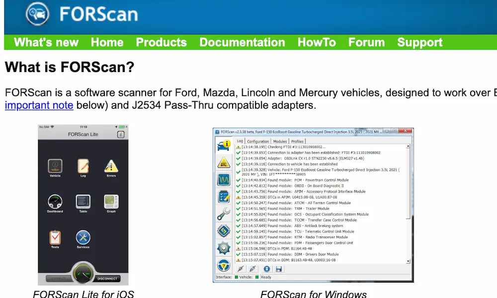
Every piezoelectric injector has a unique alphanumeric calibration code printed on its body. This code accounts for microscopic manufacturing variations in fuel flow. After physical installation, a technician must enter this code into the PCM using an advanced scan tool. Skip this step and the engine will idle rough and throw cylinder balance codes — symptoms identical to a mechanical failure.
Why do service manuals require replacing supply tubes even when they look fine?
The supply tube seals via metal-to-metal deformation at the fitting tip. Once torqued, that tip crushes into microscopic grooves specific to that installation. When loosened, the deformed metal can’t re-seat perfectly in the same grooves. The result is a microscopic leak path that’s impossible to detect visually until it becomes a high-pressure fuel leak in the engine valley.
What tools do you actually need to hit the correct angle specs?
Visual estimation isn’t good enough. Use a digital torque wrench with an integrated gyroscope that measures degrees after baseline torque, or a mechanical torque angle gauge between the ratchet and socket. For supply tubes near the firewall, offset crowfoot wrenches are often required — and if the pivot point changes, the torque value needs to be mathematically recalculated.
Can you test a piezoelectric injector with a standard multimeter?
No. Piezoelectric stacks function as electrical capacitors, not resistive coils. A multimeter resistance test will return meaningless data and can permanently short the internal crystalline stack. Proper testing requires specialized equipment capable of generating high-voltage pulses to measure capacitance and insulation integrity.
How do you safely depressurize the fuel system before loosening any fittings?
Shut the engine off and wait. The PCM opens pressure control valves shortly after shutdown and bleeds the rails to ambient pressure. Confirm the system is at zero pressure using a diagnostic scan tool monitoring the live fuel rail pressure sensor. Never loosen a high-pressure fitting without confirming zero pressure first — a pinhole leak at operating pressure can inject diesel through skin into the bloodstream.