Thinking about a Ford 302 engine rebuild but not sure where to start? Whether your 302 is smoking, knocking, or just plain tired, this guide walks you through every critical step — from cracking it open to firing it up for the first time. Stick around to the end, because the break-in procedure alone can make or break everything you’ve worked for.
What Makes the Ford 302 Worth Rebuilding
The Ford 302 cubic inch V8 — later badged as the 5.0L — isn’t just any engine. Ford introduced it in 1968 as a successor to the 289, bumping the stroke from 2.87 inches to 3.00 inches while keeping the same 4.00-inch bore. The result? More displacement in the same compact package.
What makes it special is Ford’s thin-wall casting technique, which kept the block lightweight without sacrificing rigidity. That engineering decision made the 302 a perfect fit for Mustangs, Fairlanes, and F-150s for over 30 years.
The engine evolved dramatically over its production life:
| Engine Version | Years | Key Features |
|---|---|---|
| Standard 302 Windsor | 1968–1981 | Flat-tappet, 28 oz-in balance, 2-bolt mains |
| Boss 302 | 1969–1970 | 4-bolt mains, 351 Cleveland heads, solid cam |
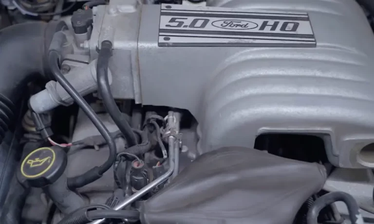
| 5.0L High Output (H.O.) | 1982–1995 | Hydraulic roller cam, 50 oz-in balance, EFI |
Each generation has different hardware, and knowing which one you’re working with is the first step before you buy a single gasket.
Identify Your Block Before You Buy Anything
This is where most first-timers go wrong. Ford stamped casting numbers on every 302 block — find them on the passenger side rear, near the starter mount. The first two characters tell you the decade and year of the design.
| Decade Code | Example | Production Era |
|---|---|---|
| C | C8AE | 1968 introduction |
| D | D4OE | 1970s emissions era |
| E | E7TE | 1980s 5.0L H.O. roller block |
| F | F1ZE | 1990s SN95 variants |
The E7TE block is a favorite among rebuilders because it accepts a hydraulic roller camshaft without modification. Earlier blocks need special “link-bar” lifters for a roller conversion.
The single most critical ID point: the external balance factor. Pre-1982 engines use a 28 oz-in balance. Post-1982 engines use 50 oz-in. Mix these up — say, bolt a 50 oz-in harmonic balancer onto a 28 oz-in crankshaft — and you’ll destroy the crank. This isn’t a detail you can skip.
Tear Down and Diagnostic Inspection
A successful Ford 302 engine rebuild starts with a complete teardown followed by hot-tank cleaning. You’re stripping every trace of oil, coolant scale, and gunk before you look at a single surface.
After cleaning, the block needs Magnetic Particle Inspection (MPI), also called Magnafluxing. An electromagnetic field plus iron powder reveals hairline cracks invisible to the naked eye. Skip this step and you risk rebuilding a cracked block.
Common crack locations on the 302:
- Between cylinder bores and coolant passages (thermal stress)
- Along oil gallery passages near freeze plugs (freeze damage)
- Main bearing webs (high-load stress)
| Inspection Method | What It Finds |
|---|---|
| Magnafluxing (MPI) | Hairline cracks in iron castings |
| Sonic testing | Exact cylinder wall thickness |
| Dial bore gauging | Taper and out-of-roundness |
| Pressure testing | Internal coolant/oil leaks |
| Straightedge + feeler gauges | Head surface warping |
For cylinder walls, you want a minimum thickness of 0.100 inches for a street engine. Performance builds should keep 0.135 to 0.200 inches on the major thrust side. Less than that, and the wall flexes under cylinder pressure, killing ring seal.
Cylinder head warping beyond 0.003 to 0.005 inches means a trip to the machine shop for resurfacing. Cracks near valve seats on cast iron heads? Just replace them — used and aftermarket Windsor heads are everywhere and cheap.
Machining: Restoring What Years of Use Took Away
Once the block passes inspection, machining brings critical dimensions back to spec.
Cylinder boring typically goes +0.030 or +0.040 inches oversize. You can go +0.060 inches, but that thins the walls enough to cause overheating problems on anything other than a mild street engine.
After boring, honing finalizes the cylinder surface. Here’s a trick many builders miss: always use a torque plate during honing. You bolt a plate to the block deck to simulate head clamping load. Without it, the bore is round on the stand but oval once the heads go on — and oval bores don’t seal rings.
Block decking flattens the top surface and sets your quench distance. A tight quench of 0.035 to 0.045 inches between the piston crown and the head creates turbulence in the combustion chamber, which improves efficiency and reduces detonation.
| Machining Operation | Spec | Why It Matters |
|---|---|---|
| Cylinder boring | +0.030″ or +0.040″ | Restores bore geometry |
| Block decking | 0.000″ (zero deck) | Optimizes quench and compression |
| Line honing | ±0.0001″ | Ensures crankshaft rotational freedom |
| Crankshaft grinding | -0.010″ or -0.020″ | Restores journal surface |
| Valve seat angle | 45 degrees | Airtight combustion seal |
The crankshaft journals get ground undersize — usually -0.010 inches — to remove scoring. When you grind the crank, match your bearing size accordingly. And before you button up the short block, get the entire rotating assembly dynamically balanced. Unbalanced assemblies destroy main bearings.
Critical Clearances: Get These Wrong and You’ll Rebuild It Again
This is the heart of a Ford 302 engine rebuild. Every clearance matters.
| Component | Specification |
|---|---|
| Main bearing clearance (street) | 0.0008″–0.0015″ |
| Main bearing clearance (performance) | 0.0020″–0.0030″ |
| Connecting rod bearing clearance | 0.0008″–0.0015″ |
| Connecting rod side clearance | 0.010″–0.020″ |
| Crankshaft end play | 0.004″–0.008″ |
| Piston pin clearance | 0.0008″–0.0010″ |
Crankshaft end play is controlled by the number three main bearing. Too much end play causes erratic timing; too little causes the thrust bearing to overheat and seize.
Piston ring gaps need special attention. For a standard street engine, set the top ring gap at 0.010 to 0.020 inches. Running nitrous or a turbo? Open that top ring gap an extra 0.004 inches to handle the extra heat. If the gap’s too tight, the ring ends butt together, and you’ll be pulling the engine apart again.
Firing Order: One Detail That Trips Up a Lot of Builders
The 302 has two different firing orders, and they’re determined entirely by the camshaft’s lobe arrangement. Install the wrong distributor cap wiring for your engine version and it won’t run right.
| Engine Version | Firing Order | Application |
|---|---|---|
| Early 302 / Standard | 1-5-4-2-6-3-7-8 | 1968–early 1980s street engines |
| Boss 302 | 1-5-4-2-6-3-7-8 | 1969–1970 performance |
| 5.0L H.O. | 1-3-7-2-6-5-4-8 | 1982–1995 Mustang and truck |
| 351 Windsor | 1-3-7-2-6-5-4-8 | All 351W variants |
Ford changed the H.O. firing order to improve main bearing load distribution and intake sound characteristics. It’s the same block, but a completely different cam — and that changes everything downstream.
Also critical: the distributor rotates counterclockwise on all 302 variants. And match your distributor gear material to your camshaft. Cast iron gears pair with flat-tappet cams; hardened steel or bronze gears go with roller cams. Wrong pairing shaves the gear teeth and sends metal through your oiling system.
Oiling System and Sealing: Don’t Let a $5 Mistake Kill a $3,000 Build
The oil pump rides at the front of the block and is driven by the distributor via a hex shaft. On performance builds, upgrade to a heavy-duty oil pump shaft — the stock shaft can twist or snap under high-volume pump loads.
Oil pump pickup clearance is one of the most overlooked specs in a 302 rebuild. The pickup screen needs to sit 0.375 to 0.500 inches from the pan floor. Too close and it starves; too far and it sucks air during hard acceleration.
For sealing, the rear main seal is your biggest leak risk. Early engines use a two-piece seal — offset the gaps so they don’t align with the main cap parting line, and dab a bit of silicone at the ends. Later engines use a more reliable one-piece design.
At the intake manifold, skip the cork end seals that come in most gasket kits. Instead, run a thick bead of high-temperature RTV silicone on the block’s China walls. It handles thermal expansion far better and won’t shrink over time.
Short Block Assembly: Precision Over Speed
Assembly happens in a clean environment — no exceptions. Even a speck of dirt can score a bearing journal.
Start with the camshaft, then the main bearings and crankshaft. Torque the main caps in three stages (25 ft-lbs, 45 ft-lbs, then 65–70 ft-lbs final) for even clamping force. Rotate the crank by hand after each cap — it should spin freely with no binding.
When installing pistons:
- Orient the chamfered side of the rod journal toward the crankshaft counterweight
- Use a ring expander — never your thumbs — to install rings without scratching the lands
- Stagger ring gaps 180 degrees apart to minimize blow-by
- Coat cylinder walls with 30-weight oil before sliding pistons in
Rod bolt torque for standard 5/16-inch bolts: 19–24 ft-lbs. Performance 3/8-inch bolts: 40–45 ft-lbs. After each piston goes in, rotate the crank again. Any resistance means something’s wrong — find it now, not after startup.
Valvetrain Geometry and Head Installation
Install head gaskets dry unless the gasket manufacturer says otherwise. Torque head bolts from the center outward in a spiral pattern, finishing at 65–72 ft-lbs for a standard Windsor.
Pushrod length is critical — especially if you’ve decked the block or milled the heads. Both operations move the rocker arms closer to the cam. If the pushrods are too long or short, the rocker tip scrubs across the valve stem instead of rolling cleanly, and your valve guides wear out fast.
For hydraulic cam setups, check rocker arm preload after achieving zero lash. If the rocker bolt needs more than two full turns to reach torque, you need shorter pushrods or shims.
Always degree the cam — use a degree wheel and dial indicator to confirm the intake lobe opens and closes at exactly the right crank position. A slight misalignment shifts your power band or causes valve-to-piston contact. Minimum clearances: 0.100 inches on intake, 0.125 inches on exhaust.
Break-In: The 30 Minutes That Determine Long-Term Reliability
Before you hit the starter, prime the oiling system. Use a drill to spin the oil pump until you see pressure on a gauge and oil weeping at the rocker arms. This protects bearings during that critical first revolution.
Flat-tappet cam break-in procedure:
- Start the engine and immediately bring it to 2,000–2,500 RPM
- Hold that RPM for 20–30 minutes — this gives the cam lobes enough splash lubrication to work-harden
- Monitor oil pressure and coolant temp the entire time
- Any unusual noise or pressure drop = shut it down immediately
| Break-In Phase | Action | Duration |
|---|---|---|
| Pre-start oil prime | Spin pump with drill | Until pressure shows |
| Initial fire-up | 2,000–2,500 RPM | 20–30 minutes |
| Thermal cycling | Idle then cool completely | 3 cycles |
| Ring seating | Short load bursts | First 500 miles |
| First oil change | Drain and replace | At 100 miles |
Don’t baby the engine by idling it for extended periods — that glazes the cylinder walls and prevents rings from ever seating. Short bursts of load followed by deceleration is what forces the rings against the walls to seal properly.
Use a high-ZDDP break-in oil for the first fill. Change the oil at 100 miles to flush out assembly lube and metal particles. Hold off on full synthetic until 1,000–2,000 miles — synthetic’s low friction actually slows ring seating.
Performance Upgrades: What You Can Realistically Expect
A stock rebuild nets around 200–225 horsepower. But the 302 platform has serious headroom.
| Build Level | Displacement | Target HP | Key Parts |
|---|---|---|---|
| Budget street | 302 ci | ~300 HP | GT40 heads, E303 cam, 600 CFM carb |
| High-performance street | 302 ci | ~380 HP | Aluminum 170cc heads, roller cam |
| Stroker naturally aspirated | 347 ci | ~450 HP | Forged 3.4″ crank, 190cc heads, EFI |
| Max effort | 347 ci | 500+ HP | Aftermarket block, forced induction |
The 347 stroker — using a 3.400-inch crankshaft — is the most popular displacement bump. It adds torque across the whole RPM range without changing the external dimensions. The trade-off? You’ll need to notch the cylinder bores and oil pan rails for connecting rod clearance.
One hard limit to respect: the stock 302 block is prone to splitting through the main bearing webs around 500 horsepower, especially under boost. If you’re targeting 500+ HP, start with an aftermarket Dart block or a Boss 302 casting. Those blocks have thicker webbing, beefier main caps, and the metallurgy to handle serious power.
Ongoing Maintenance After Your Rebuild
A rebuilt 302 needs consistent attention to stay healthy:
- Flat-tappet engines: Always run oil with adequate ZDDP levels. Modern API oils have reduced zinc content, which accelerates cam lobe wear
- Check ignition timing periodically — a misaligned distributor quietly kills power and efficiency
- Keep the cooling system clean — the thin-wall casting is sensitive to overheating, and thermal stress cracks follow quickly
- Inspect spark plugs every season — they tell you exactly what’s happening inside the combustion chamber
- Watch for intake manifold vacuum leaks — the 302’s common China wall leak point causes erratic idle and lean mixtures if the RTV seal fails
A rebuilt 302 done right doesn’t just restore original performance — it often surpasses it. Every measurement you take, every clearance you verify, and every torque spec you hit adds up to an engine that’ll outlast the car it’s sitting in.