Got a misfire? Planning an LS swap? Or just curious why your LS sounds different from an old-school small-block? The LS1 firing order is the answer to more questions than you’d expect. This guide breaks down everything — from why GM changed it, to wiring your coils correctly the first time.
What Is the LS1 Firing Order?
The LS1 firing order is 1-8-7-2-6-5-4-3.
Every Gen III and Gen IV LS V8 uses this same sequence. It doesn’t matter if you’re running a 5.7L LS1, a 6.0L LS2, or a 6.2L LS3 — the firing order never changes across the entire LS family tree.
This isn’t the firing order from your grandfather’s small-block. The old Gen I/II small-block Chevy fired in the sequence 1-8-4-3-6-5-7-2. GM ditched that sequence completely when they designed the LS from scratch in the mid-1990s. Here’s why that matters more than you think.
Why GM Changed the Firing Order
The traditional 1-8-4-3-6-5-7-2 sequence had one nasty flaw. Cylinders 5 and 7 — both sitting at the rear of the driver-side bank — fired back to back, separated by only 90 degrees of crankshaft rotation.
That’s a problem for two big reasons:
- Heat concentration: The water pump pushes fresh coolant in at the front. By the time it reaches the rear cylinders, it’s already hot. Firing 5 and 7 consecutively in the hottest part of the engine created a thermal disaster zone — head gasket failures, localized boiling, and knock.
- Torsional stress: Consecutive firing compounds the twisting force on the crankshaft. The number four main bearing took a brutal beating, wearing faster and generating parasitic friction.
Pro Stock drag racers figured out the fix before GM did. Engine builders at firms like Reher-Morrison pioneered what’s called the 4/7 swap — a custom camshaft that swapped the valve events of companion cylinders 4 and 7. The result? 8-10 horsepower gains and a cooler, smoother engine. Consistently.
When GM designed the LS from a blank slate, they took the 4/7 swap one step further. They also swapped companion cylinders 2 and 3. The combined result of both swaps is the permanent 1-8-7-2-6-5-4-3 firing order baked into every LS engine ever built.
How Companion Cylinders Work (And Why It Matters)
In a cross-plane V8, the crankshaft journals sit at 90-degree intervals. That means two pistons always reach Top Dead Center simultaneously — they’re called companion cylinders.
One piston hits TDC on the compression stroke. Its companion hits TDC on the exhaust stroke. Exactly 360 degrees later, they swap roles.
The LS companion cylinder pairings are:
| Companion Pair | Bank Locations |
|---|---|
| Cylinders 1 & 6 | Driver Front / Passenger Rear |
| Cylinders 5 & 8 | Driver Rear / Passenger Rear |
| Cylinders 4 & 7 | Passenger Middle / Driver Rear |
| Cylinders 2 & 3 | Passenger Front / Driver Front |
Because these pairs always reach TDC together, you can swap their firing sequence by simply changing the camshaft lobe orientation and re-routing the ignition wiring. That’s exactly what the 4/7 swap does — and what GM permanently engineered into the LS platform.
LS1 Firing Order vs. Old Small-Block: The Real Difference
| V8 Architecture | Firing Order |
|---|---|
| Gen I / II Small-Block Chevy | 1-8-4-3-6-5-7-2 |
| Aftermarket 4/7 Swap | 1-8-7-3-6-5-4-2 |
| Gen III / IV LS V8 (All) | 1-8-7-2-6-5-4-3 |
| Ford Coyote 5.0L | 1-5-4-8-6-3-7-2 |
The LS firing order moves the consecutive firing pair from the hot rear of the engine (cylinders 5 and 7) to the cool front (cylinders 1 and 3). Cylinders 1 and 3 sit directly next to the water pump, bathed in the freshest coolant entering the block. Consecutive combustion there? No problem. Uniform cylinder temperatures allow more aggressive ignition timing — which means more torque.
LS Cylinder Numbering: Which Cylinder Is Where?
You can’t wire, tune, or troubleshoot an LS engine without knowing the cylinder layout. GM numbers the cylinders front to back, alternating between banks.
- Driver Side (Left Bank) — Bank 1: Cylinders 1, 3, 5, 7 (front to rear)
- Passenger Side (Right Bank) — Bank 2: Cylinders 2, 4, 6, 8 (front to rear)
Cylinder 1 is always the furthest forward cylinder in the engine bay, on the driver side. That’s your anchor point for everything else.
Bank 1 vs. Bank 2: Why It Matters for O2 Sensors
Your PCM uses Bank 1 and Bank 2 designations to track oxygen sensor data and adjust fuel trims independently per side. Getting this wrong means your PCM overcorrects one bank while starving the other.
| Sensor | Physical Location | Function |
|---|---|---|
| Bank 1, Sensor 1 | Driver Side, Upstream | Primary A/F ratio monitoring |
| Bank 1, Sensor 2 | Driver Side, Downstream | Catalyst efficiency monitoring |
| Bank 2, Sensor 1 | Passenger Side, Upstream | Primary A/F ratio monitoring |
| Bank 2, Sensor 2 | Passenger Side, Downstream | Catalyst efficiency monitoring |
Quick tip: If you don’t know which sensor is which, unplug one while the engine runs. The PCM triggers an open-circuit fault code instantly, identifying the bank on your scan tool.
Ignition Coil Wiring: Don’t Get This Wrong
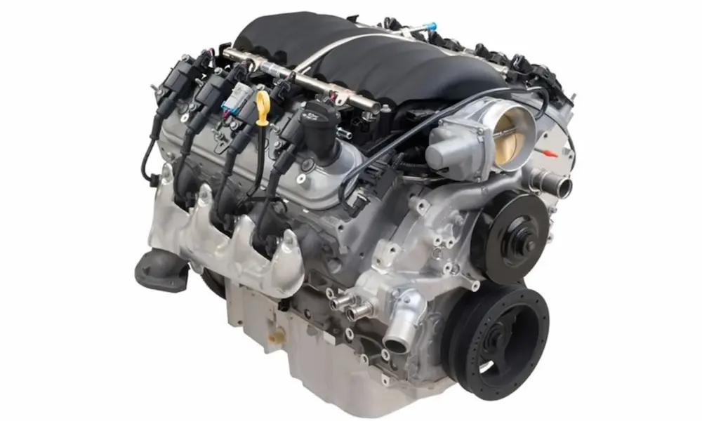
The LS uses a coil-near-plug ignition system — eight individual coils mounted directly on the valve covers, one per cylinder. Each coil fires directly based on the 1-8-7-2-6-5-4-3 sequence commanded by the PCM.
Each coil connector has four wires:
- Ground (Black/Black-White) — Must bolt to bare metal on the cylinder head
- Low Reference / Sensor Ground (Brown)
- 12V Switched Ignition Power (Pink)
- Ignition Control Signal / Trigger — Unique color per cylinder
The trigger wire color is your only way to identify each coil’s position on the harness. Here’s the factory color code layout:
| Driver Side Cylinder | Trigger Wire Color | Passenger Side Cylinder | Trigger Wire Color |
|---|---|---|---|
| Cylinder 1 (Front) | Purple | Cylinder 2 (Front) | Red |
| Cylinder 3 | Light Blue | Cylinder 4 | Green |
| Cylinder 5 | Green | Cylinder 6 | Light Blue |
| Cylinder 7 (Rear) | Red | Cylinder 8 (Rear) | Purple |
The Red wire always goes to the front cylinder on each bank. Flip the sub-harness bracket backward and the PCM sends cylinder 7’s spark command to cylinder 1. The result is violent intake backfiring and a no-idle condition.
Standalone ECU Notes
If you’re running a Haltech or Holley EFI system, set the LS coils to Constant Charge mode with a Falling Edge trigger. Rising edge will overheat the internal igniters and melt the coil housing. At high RPM, install a dedicated 30-amp relay for every pair of coils — the stock electrical setup can’t handle the current draw.
The PCM and Sequential Fuel Injection
The LS1 PCM — hardware numbers like 12200411 — fires each fuel injector individually, timed precisely to the intake valve opening. It maps eight injectors (labeled A through H internally) directly to the 1-8-7-2-6-5-4-3 firing sequence.
Here’s how that maps out:
- Injector A → Cylinder 1 (Bank 1)
- Injector B → Cylinder 8 (Bank 2)
- Injector C → Cylinder 7 (Bank 1)
- Injector D → Cylinder 2 (Bank 2)
- Injector E → Cylinder 6 (Bank 2)
- Injector F → Cylinder 5 (Bank 1)
- Injector G → Cylinder 4 (Bank 2)
- Injector H → Cylinder 3 (Bank 1)
Try running an LS PCM on an old Gen I small-block without updating this table? The PCM commands fuel corrections to the wrong physical bank entirely. One bank floods. The other starves. The engine won’t run.
24x vs. 58x Reluctor Wheels: Critical for Swaps
The LS uses a precision reluctor wheel on the crankshaft — paired with a crankshaft position sensor — to track engine position for ignition timing.
- Gen III LS (LS1, LM7, LQ4): 24-tooth reluctor wheel, black sensor
- Gen IV LS (LS2, LS3, LS7): 58-tooth reluctor wheel, gray sensor
These two systems are completely incompatible. A Gen III PCM can’t process the 58x signal. A Gen IV PCM can’t process the 24x signal. Mixing them without an aftermarket digital converter box means the engine won’t start — full stop. Check your sensors before you swap anything.
The smooth crankshaft rotation created by the 1-8-7-2-6-5-4-3 firing order is part of why the reluctor reads accurately. Reduced torsional vibration keeps the reluctor teeth aligned with the sensor, preventing timing scatter.
Diagnosing LS Misfires
The LS PCM tracks crankshaft acceleration using the reluctor wheel. When a cylinder misfires, the crank doesn’t accelerate during that power stroke. The PCM increments a misfire counter for that specific cylinder instantly.
Use an OBD-II scanner to read live misfire counters. Then cross-reference the firing order to see if the misfire pattern points to one bank, one coil driver, or one injector circuit.
For a quick physical check, use a non-contact infrared thermometer on the exhaust primaries at the cylinder head flange. A healthy cylinder runs above 500°F. A dead cylinder stays cold. It’s one of the fastest ways to isolate a misfire without electronics.
Three common LS misfire causes:
- Bad cylinder head grounds: Painted-over grounding points introduce resistance into the ignition circuit. Random misfires across multiple cylinders that come and go? Check your grounds first. Scrape to bare metal.
- Crank/cam sync errors: Aftermarket high-lift cams can push the cam sensor trigger edge too close to the crank signal, confusing the PCM’s position calculation. Fix it in the tuning software by adjusting TDC offset values.
- Crossed O2 sensors: If Bank 1 reads lean and the PCM commands more fuel to Bank 2 because the sensors are swapped, you get one flooded bank and one that’s starving. Unplug sensors one at a time while running to confirm which bank is which.
Spark Plug Wire Maintenance
The LS uses short spark plug wires routed close to exhaust manifolds. Heat kills them faster than anything else. Once the silicone insulation cracks, high-voltage current arcs directly to the nearest ground — usually the exhaust manifold — instead of jumping the spark plug gap.
That’s called spark leak. The cylinder goes dead under load. Unburnt fuel dumps into the catalytic converter and can destroy it.
When building custom-length wires for coil-relocation builds, follow the proper assembly steps: measure with the wire routed fully, strip exactly 1/2 to 5/8 inch of insulation without nicking the conductor core, fold the core back over the insulation, crimp with a ratcheting spark plug wire crimper, and verify resistance with a multimeter. A properly built spiral-core wire reads approximately 80–87 ohms per inch. Higher than that means a damaged core — cut it off and start over.
Route every wire away from exhaust components with adequate clearance. This isn’t optional maintenance.
LS Engine Family: Same Firing Order, Different Everything Else
The 1-8-7-2-6-5-4-3 firing order is universal across the entire LS family. But the physical engines differ substantially. Here’s a quick reference:
| Engine Code | Generation | Displacement | Block | Bore (in) | Stroke (in) |
|---|---|---|---|---|---|
| LM7 | Gen III | 5.3L | Cast Iron | 3.780 | 3.622 |
| LS1 | Gen III | 5.7L | Aluminum | 3.898 | 3.622 |
| LQ4 | Gen III | 6.0L | Cast Iron | 4.000 | 3.622 |
| LS2 | Gen IV | 6.0L | Aluminum | 4.000 | 3.622 |
| LS3 | Gen IV | 6.2L | Aluminum | 4.065 | 3.622 |
| LS7 | Gen IV | 7.0L | Aluminum | 4.125 | 4.000 |
Most LS variants share the same 3.622-inch stroke. Displacement differences come almost entirely from bore diameter changes.
Cylinder head port design splits into two categories you need to know for compatibility:
- Cathedral Port heads (Gen III): Casting numbers ending in 241, 243, 706, 799, 853, 317 — excellent low-RPM torque
- Rectangle Port heads (Gen IV): Casting numbers ending in 821, 823, 716, 845 — massive high-RPM flow for 500+ hp builds
Cathedral and rectangle port intake manifolds aren’t interchangeable. Confirm your head casting numbers before ordering parts.
The Bottom Line on LS1 Firing Order
The LS1 firing order — 1-8-7-2-6-5-4-3 — isn’t just a sequence GM picked arbitrarily. It’s the product of racing-derived engineering, thermal physics, and computer modeling that solved real problems the old small-block never could. It redistributes bearing loads, moves heat away from the vulnerable rear cylinders, and enables the high-resolution electronic management that makes the LS one of the most tunable engines ever produced.
Get the firing order, cylinder numbering, coil wiring colors, and bank designations right — and your LS build goes together cleanly. Get any of them wrong, and you’re chasing gremlins for weeks.