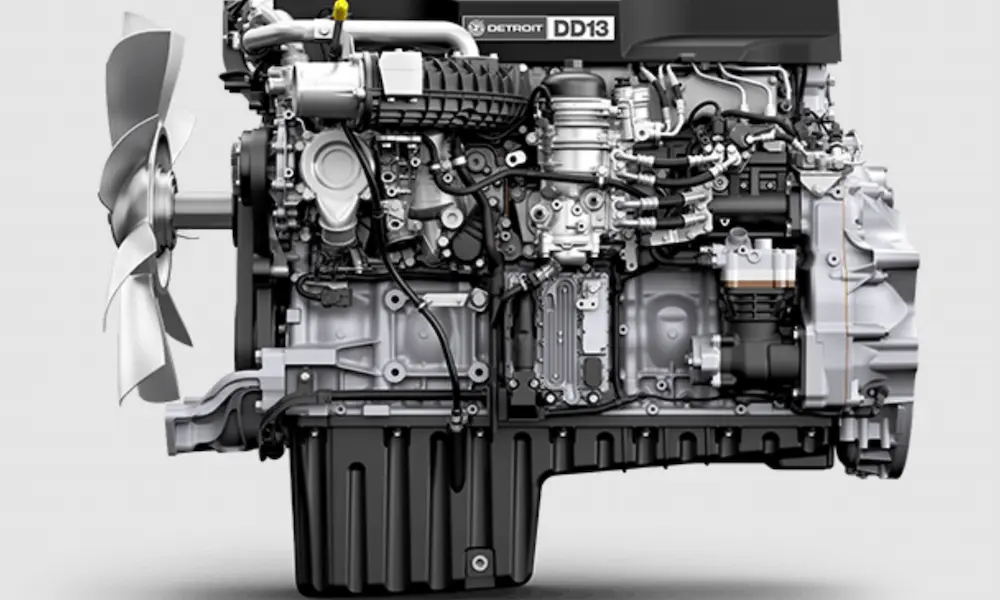
Got a Volvo D13 that’s ticking, losing power, or eating through DPF regens? The overhead might be overdue. This guide walks you through every step of the Volvo D13 valve adjustment process — from prep and safety to final torque specs — so you get it right the first time.
Why the Volvo D13 Valve Adjustment Actually Matters
The D13 is a 12.78-liter inline-six diesel. It fires in a 1-5-3-6-2-4 sequence and runs a single overhead camshaft that drives intake valves, exhaust valves, and unit injectors through rocker arms and floating valve bridges.
Over time, thermal cycling and mechanical stress shift those critical clearances. Here’s what happens when you ignore them:
- Too tight: Valves can’t seat fully. Heat can’t transfer to the coolant. You get burnt valves and compression loss.
- Too loose: Rocker arms slam the valve bridges. You hear ticking, accelerate wear, and lose cylinder breathing efficiency.
- Engine brake issues: The Volvo Engine Brake (VEB) depends on exact rocker arm tolerances to work. Neglect the overhead, and you lose retarding power on steep grades — a real safety concern.
Keeping these clearances dialed in directly protects fuel economy, emission compliance, and engine longevity.
When to Schedule Your Volvo D13 Valve Adjustment
Volvo sets clear intervals based on your duty cycle. Here’s how it breaks down for the U.S. market:
| Service Event | Normal Duty | Severe Duty |
|---|---|---|
| Initial valve adjustment | 150,000 miles / 12 months | 150,000 miles / 12 months |
| Subsequent adjustments | 300,000 miles / 24 months | 200,000 miles / 12–24 months |
| Oil & filter change | 45,000 miles / 1,300 hours | 25,000 miles / 625 hours |
| DPF cleaning | 400,000 miles / 10,000 hours | 250,000 miles / 4,500 hours |
| Fan & accessory belts | 300,000 miles / 36 months | 150,000 miles / 12 months |
Normal duty means highway miles at 6+ MPG with minimal idling. Severe duty covers vocational work, heavy hauls, extreme temps, or anything under 5 MPG.
One rule most fleets miss: If your idle time tops 30% of total engine hours, drop to the next lower service interval category. Idling burns engine hours without adding odometer miles — your valvetrain doesn’t know the difference.
Safety First: How to Prep the Engine Correctly
The D13 valve adjustment must be done on a cold engine — block and coolant temperatures below 140°F. Adjusting hot gives you falsely tight measurements that go dangerously loose once everything cools down.
Before you touch anything mechanical:
- Park on level ground, transmission in neutral, parking brake set.
- Disconnect the negative battery cables from both batteries.
- Pull fuse F40 to disable the ECU and prevent any accidental cranking.
Accidental engine start during crankshaft rotation is a serious hazard. Don’t skip these steps.
Valve Cover Removal Checklist
Work through this sequence to clear the top of the cylinder head:
- Remove the air filter restriction gauge
- Loosen clamps and pull the air compressor fresh air pipe
- Unbolt and remove the EGR crossover pipe, venturi outlet pipe, and mixer inlet pipe
- Detach the aftertreatment fuel injector harness clips from the valve cover
- Remove the crankcase ventilation housing fasteners and strap the housing aside
- Remove the spring-loaded valve cover bolts and carefully lift the cover clear of the camshaft gear
Always replace the valve cover gasket at every overhead service. It’s cheap insurance against oil leaks.
Installing the Flywheel Turning Tool
Pull the access plug from the lower right side of the flywheel housing. Install Volvo flywheel turning tool part number 88800014. You can also use a 32mm socket on the crankshaft belt pulley.
Critical rule: Only rotate the engine clockwise when viewed from the front. Turning it backward loads the gear train wrong and ruins your adjustment accuracy.
Reading the Camshaft Marks
Volvo machines position marks on the front end of the camshaft. These align with a stamped reference line on the front bearing cap. The marks tell you when each cylinder’s cam lobes sit on their base circle — the flat, no-lift section where adjustments happen.
Here’s where engines with and without the VEB differ:
| Engine Configuration | Marks 1–6 Used For | Secondary Marks Used For |
|---|---|---|
| No engine brake | Intake, exhaust, and injector (all three per cylinder) | N/A |
| With Volvo Engine Brake (VEB) | Intake valves and unit injectors only | E1–E6 marks for exhaust valves and brake rockers |
Pro tip: Use a paint marker to mark each rocker arm as you finish it. If you get interrupted mid-job, those marks prevent costly double-adjustments or missed cylinders. Adjusting on the wrong mark can bend valves and destroy the engine.
Intake Valve Adjustment: Step-by-Step
Bar the engine over until the target camshaft mark aligns with the bearing cap reference line.
- Push firmly down on the back of the intake rocker arm to purge any trapped oil and confirm the roller sits on the base circle.
- Slide a feeler gauge between the valve bridge and the adjustment screw plunger.
- Target clearance: 0.20mm (0.008 inches), tolerance ±0.05mm (±0.002 inches).
- The gauge should slide with a light, smooth drag. No movement means it’s too tight. Free-sliding means it’s too loose.
- Loosen the lock nut and turn the adjusting screw until you hit that light drag.
- Hold the adjusting screw stationary while torquing the lock nut to 38 Nm (28 ft-lbs).
- Re-check the clearance after torquing — thread stretch often tightens things slightly.
- Mark the rocker arm with a paint pen.
Unit Injector Preload: Getting It Right
The D13 uses mechanical unit injectors — the camshaft physically drives a plunger to generate injection pressure. There’s no clearance gap here. You need a precise preload.
Here’s the process:
- While on the same camshaft mark as the intake, move to the injector rocker arm.
- Completely loosen the lock nut and back off the adjusting screw until it loses contact with the injector plunger.
- Slowly turn the screw clockwise until it just makes solid contact with the plunger — but don’t compress the internal spring. Zero clearance only.
- From that zero point, turn the screw exactly 4 flats (240 degrees) clockwise.
- Hold the screw stationary and torque the lock nut to 52 Nm (38 ft-lbs).
- Mark the rocker arm.
Why 4 flats? A hex head has 6 sides at 60° each. Four flats = 240° of rotation. This precise depth preloads the injector spring so the plunger generates maximum injection pressure without bottoming out and cracking the injector body.
Exhaust Valve Adjustment: Two Different Procedures
This is where the job splits depending on whether your D13 has the Volvo Engine Brake.
No Engine Brake
Simple. Adjust the exhaust valve on the same numerical camshaft mark (1–6) you used for the intake and injector.
- Push down on the back of the exhaust rocker arm
- Insert feeler gauge between the valve bridge and adjustment screw
- Target: 0.80mm (0.031 inches), tolerance ±0.05mm
- Adjust, torque lock nut to 38 Nm (28 ft-lbs), re-check, mark it
With Volvo Engine Brake (VEB)
This takes more steps. Work through it carefully.
- Before starting exhaust adjustments, loosen (don’t remove) the brake rocker arm leaf spring bolts.
- Bar the engine to the E-mark (E1–E6) on the camshaft.
- Adjust the exhaust valve on the cylinder number matching that E-mark.
Exhaust bridge clearance with VEB:
- Target: 1.00mm (0.039 inches)
- Some engines use a threaded plunger. Others use a shim system on top of the valve bridge.
If your engine uses shims:
- When removing the shim retaining screw, always counter-hold the valve yoke with a separate tool. Failing to do this can bend the valve stem — catastrophic damage.
- Clean the bridge and all shims thoroughly before measuring.
- Shims come in 0.05mm (0.002-inch) increments, with thickness laser-etched on the surface.
- Maximum two shims per bridge — no exceptions. Three or more creates structural instability under rocker arm load.
- If two shims are needed, match them as closely in thickness as possible.
- Torque the retaining screw to 38 Nm (28 ft-lbs).
Engine brake rocker arm clearance:
- Leave the 0.039-inch feeler gauge in place between the exhaust rocker and bridge.
- Place a 2.5mm (0.100-inch) feeler gauge between the brake rocker roller and the camshaft lobe.
- Target: 2.5mm ±0.07mm (0.100 ±0.003 inches).
- If adjustment is needed: loosen the lock nut, back off the adjuster 0.5–1 full turn, then tighten the adjuster until contact is made, then add a half turn more so the yoke moves slightly.
- Back the adjuster out slowly until the 2.5mm gauge slides with moderate effort.
- Torque the lock nut to 52 Nm (38 ft-lbs).
- After all cylinders are done, re-tighten the leaf spring bolts.
Quick Reference: All D13 Valve Clearance and Torque Specs
| Component | Metric Clearance | Imperial Clearance | Lock Nut Torque |
|---|---|---|---|
| Intake valve | 0.20 ±0.05mm | 0.008 ±0.002 in | 38 Nm / 28 ft-lbs |
| Exhaust valve (no VEB) | 0.80 ±0.05mm | 0.031 ±0.002 in | 38 Nm / 28 ft-lbs |
| Exhaust valve (with VEB) | 1.00 ±0.05mm | 0.039 ±0.002 in | 38 Nm / 28 ft-lbs |
| Engine brake rocker | 2.5 ±0.07mm | 0.100 ±0.003 in | 52 Nm / 38 ft-lbs |
| Unit injector preload | Zero + 4 flats (240°) | Zero + 4 flats (240°) | 52 Nm / 38 ft-lbs |
| Shim retaining screw | N/A | N/A | 38 Nm / 28 ft-lbs |
Rocker Shaft Torque Sequence (Full Removal Jobs)
If you pulled the rocker shaft for a cam replacement or injector cup job, reinstallation demands a 10-stage torque sequence. Rushing this step bends or cracks the shaft.
| Stage | Bolts | Action |
|---|---|---|
| 1 | 1–7 | 15 ±5 Nm |
| 2 | 11, 10, 12, 9, 13, 8, 20 | Gradually lower shaft without damage |
| 3 | 1–7 | 90 ±5° angle tighten |
| 4 | 8–13, 20 | Loosen completely |
| 5 | 8–13, 20 | 60 ±5 Nm |
| 6 | 14–19 | 40 ±3 Nm |
| 7 | 14–19 | 120 ±5° angle tighten |
| 8 | 8–13 | Loosen completely |
| 9 | 8–13 | 40 ±3 Nm |
| 10 | 8–13, 20 | 120 ±5° angle tighten |
Only after completing all 10 stages should you begin individual valve and injector adjustments.
Common Pitfalls That Trip Up Even Experienced Techs
Ticking and Low Oil Pressure After the Overhead
You finished the job and now the engine ticks and the oil pressure warning is on. Before you condemn the oil pump, pull the valve cover and inspect the rocker arms.
D13 rocker arms contain small brass oil regulating pins. These pins fracture and fall into the oil pan. Missing pins cause massive internal oil pressure loss at the top of the engine. The result: ticking noise and low oil pressure warnings at idle — sometimes dropping well under 20 PSI. Replace the affected rocker arms to fix it.
Also watch out for sensor mix-ups. Volvo uses the same thread pitch for oil pressure and crankcase pressure sensors — but they’re calibrated differently. The oil pressure sensor has a black housing. The crankcase pressure sensor has a yellow housing. Swap them accidentally and the ECM gets corrupt data, triggering erratic warnings and drivability issues.
Hard Start After Heat Soak Isn’t Always the Overhead
If the engine cranks long before firing after a hot shutdown, and you’re seeing white smoke at startup or a rough idle, don’t assume the injector preload is off. These are classic injector cup failure symptoms.
Cracked injector cups let combustion gas bleed back through the fuel system on shutdown. The next start requires extended cranking to re-prime the fuel rails.
How to confirm it: Install a clear section of tubing in the fuel return line at the front of the cylinder head near the lifting bracket. Run the engine. If you see continuous air bubbles, combustion gas is entering the fuel system. That’s a cup replacement job — not an overhead issue.
Replacing the cups requires specialized extraction tools. Older copper cups can balloon outward into the cylinder head, making removal difficult. Clean the cup bores thoroughly with stainless steel bore brushes before installing new cups — a dirty bore causes rapid repeat failure.
FAQ: Volvo D13 Valve Adjustment
What does the Volvo D13 valve adjustment interval look like for normal highway duty?
The initial adjustment hits at 150,000 miles or 12 months. After that, it’s every 300,000 miles or 24 months for standard over-the-road applications.
Why must the engine be cold for a D13 valve adjustment?
Factory specs account for thermal expansion. Adjusting hot creates measurements that go too loose once the metal contracts. Tight valves can’t seat properly, which prevents heat transfer and burns the valve face.
Why do you turn the injector screw exactly 4 flats?
Four flats equals 240° of rotation. Starting from true zero contact — without compressing the injector spring — this rotation preloads the spring to the exact depth needed for full injection pressure without bottoming the plunger.
Can I stack 3 shims on the VEB exhaust bridge?
No. Two shims maximum, and they should be close in thickness. Three shims create structural instability under the rocker arm’s downward force. Select thicker individual shims if the gap is large.
What’s different about adjusting exhaust valves on a VEB-equipped D13?
On a standard engine, exhaust valves get adjusted on marks 1–6 alongside the intake and injector. On a VEB engine, marks 1–6 only cover intake and injectors. Exhaust valves and the brake rocker need the E-marks (E1–E6), and the exhaust bridge clearance widens to 0.039 inches instead of 0.031 inches.
How does idling affect my D13 valve adjustment schedule?
If idle time exceeds 30% of total engine hours, Volvo requires you to drop to the next lower maintenance interval. A truck on the 300,000-mile schedule moves to 200,000 miles. Idling racks up engine wear without adding odometer miles.
What causes low oil pressure right after a valve adjustment?
Check for missing brass oil regulating pins inside the rocker arms. These pins fracture and fall into the oil pan, causing major internal oil pressure loss at the top of the engine. Replace the affected rockers to restore proper lubrication and pressure.
How do I confirm a rough idle is an injector cup problem rather than a valve adjustment issue?
Install a clear fuel line section in the return port at the front of the cylinder head. Bubbles in the fuel return line while the engine runs confirm combustion gas is entering the fuel system — which points to failed injector cups, not the overhead.