Got a slipping 4R100 on your Super Duty or Power Stroke diesel? This guide covers everything from why these transmissions fail to exactly how you rebuild one right. We’ll walk through the failure points, tear-down sequence, clutch specs, valve body tricks, and post-rebuild testing. Stick around — the details here could save you from doing this job twice.
What Makes the 4R100 Special (And Where It Struggles)
Ford introduced the 4R100 for the 1998–1999 model years as a direct upgrade over the E4OD. It was built to handle the brutal torque of the 7.3L Power Stroke diesel and the 6.8L Triton V10. You’ll find it behind F-250 through F-550 trucks, E-Series vans, the Ford Excursion, and the Lincoln Navigator.
From the factory, it handles around 500 ft-lbs of input torque. With the right upgrades during a 4R100 transmission rebuild, that number jumps to 800–1,000+ ft-lbs.
Here’s a quick look at the core specs:
| Parameter | Specification |
|---|---|
| 1st Gear Ratio | 2.71:1 |
| 2nd Gear Ratio | 1.54:1 |
| 3rd Gear Ratio | 1.00:1 (Direct Drive) |
| 4th Gear Ratio | 0.71:1 (Overdrive) |
| Reverse Ratio | 2.18:1 |
| Dry Weight | ~270 lbs |
| Factory Torque Rating | ~500 ft-lbs |
| Upgraded Torque Capacity | 800–1,000+ ft-lbs |
Why 4R100 Transmissions Fail
Before you start a 4R100 transmission rebuild, you need to understand why it failed. The same weak points kill these units over and over.
Torque Converter Clutch Failure
The factory torque converter clutch uses a thin friction disc that’s fine for light-duty use. Under towing loads or high heat, it slips, glazes, and falls apart. When it does, metallic debris floods the entire hydraulic circuit, scoring pump gears and destroying clutch packs. Everything downstream pays the price.
Valve Body Bore Wear
The aluminum valve body wears fast. The pressure regulator, line regulator, and 1-2 shift valve bores all wear oval over time. Worn bores mean pressure drops, delayed shifts, and heat. That heat burns clutches. It’s a domino effect.
Center Support Feed Bolt Backing Out
This one catches people off guard. In diesel applications, engine vibration slowly backs out the center support feed bolts inside the case. The result looks like total transmission failure — no pressure, no movement. The actual fix is resealing those feed bolt passages. Always check these bolts during any 4R100 rebuild.
Overdrive Clutch Pack Burnout
Fourth gear demands a lot from the overdrive clutch pack. The factory pack doesn’t have enough friction material to handle it under sustained load. Drop in line pressure from a worn valve body, and those overdrive clutches slip and burn up fast.
Bypass Valve Clogging
The external cooler circuit has a bypass check valve that opens between 50–60 PSI to warm the fluid quickly during cold starts. Fine debris from a failing transmission clogs this valve in the open position. Hot fluid then bypasses the cooler entirely. Seals harden, clutches burn.
Tools You Need Before You Start
A 4R100 transmission rebuild isn’t a job you wing. You need the right tools.
Basic hand tools:
- Complete socket set (standard and metric)
- Combination wrenches
- Slip-joint and needle-nose pliers
- Flat-head and Phillips screwdrivers
- Soft-faced mallet and pry bar
Specialized transmission tools:
- Hydraulic transmission jack + heavy-duty stands (the case weighs 270 lbs)
- Heavy-duty snap ring pliers (internal and external)
- Bearing pullers and seal extractors
Precision measuring tools:
- Dial indicator with magnetic base (for input shaft endplay)
- Digital calipers
- Feeler gauges
- High-pressure gauge (up to 350 PSI with long hose)
Diagnostic equipment:
- Vacuum test stand (target: 25 in/Hg minimum on center support circuits)
Safety first: wear eye protection and chemical-resistant gloves throughout the entire process. ATF and solvent cleaners aren’t kind to skin or eyes.
Tear-Down Sequence
Follow this order to avoid damaging the aluminum case and losing critical selective shims.
- Remove all external bracketry, shift linkages, and the manual lever position sensor
- Slide the torque converter off the input shaft and inspect the pilot hub for scoring
- Invert the transmission, drain fluid, and pull the pan and filter
- Unbolt and remove the solenoid pack (two 10mm bolts at the pump casing)
- Remove accumulator valve body, lower valve body, and main valve body
- Pull the steel separator plate and gaskets
- Retrieve all eight 5/16″ case checkballs plus the EPC poppet ball and spring
- Unbolt the pump perimeter bolts and extract the front pump with a slide hammer
- Remove the overdrive clutch selective snap ring, backing plate, and clutch pack
- Remove the overdrive planetary carrier, coast clutch drum, and center shaft
- Unbolt the three center support feed bolts (two M12, one M10)
- Compress and remove the center support snap ring
- Carefully slide out the center support, direct clutch drum, forward clutch drum, sunshell, planetary gear sets, and output shaft
- Extract the low/reverse one-way clutch inner race from the rear of the case
- Unbolt and remove the parking pawl abutment and parking rod guide plate
Critical Sub-Assembly Upgrades
A standard overhaul replaces worn parts. A heavy-duty 4R100 transmission rebuild fixes the design weaknesses. Here’s where to focus your upgrades.
Oil Pump Clearances
The Gerotor pump must hold tight clearances. Check and machine the pump halves flat to within 0.002 inches. Verify these clearances with feeler gauges:
- Outer gear to pump body: max 0.004 inches
- Lobe-to-lobe clearance: 0.004–0.006 inches (anything over 0.006″ kills converter clutch life)
- Gear pocket clearance: 0.001–0.0022 inches
Low Drum TIG Welding
Heavy towing hammers the low drum with rotational shock. TIG weld every third spline around the drum perimeter. This stops spline cracking before it starts.
Forward Clutch Drum
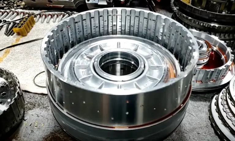
The forward clutch is active in all four forward gears. If your unit uses a factory “half-spline” drum, replace it with a full-spline, 4140 heat-treated billet steel forward clutch drum. It’s not optional on diesel builds.
Low Roller Clutch Upgrade
Early units used a 16-roller low roller clutch. Upgrade to the late-design 17-roller assembly with:
- A matching inner race at 3.385 inches diameter (replacing the early 3.189-inch race)
- A stamped steel reverse clutch hub with wider grooves and a larger cam diameter
Intermediate Sprag
Replace the factory intermediate sprag with a heavy-duty Borg Warner 45-element sprag. More elements = more contact area = no rollover under hard shifting.
Bypass Valve Fix
Kill the bypass problem entirely. Install a solid bypass nut in place of the check valve. All fluid routes through the cooler at all times.
Clutch Pack Clearances and Heavy-Duty Stackups
Soak all new friction plates in the correct ATF for 15–20 minutes before installation. Dry plates glaze immediately at startup.
Here are the clutch pack clearance specs:
| Clutch Pack | Application | Clearance Range |
|---|---|---|
| Forward | All | 0.030″–0.055″ |
| Intermediate | All | 0.029″–0.063″ |
| Coast | All | 0.030″–0.050″ |
| Direct | All | 0.045″–0.081″ |
| Overdrive | Gas engines | 0.027″–0.052″ |
| Overdrive | Diesel engines | 0.039″–0.064″ |
| Reverse | Gas engines | 0.027″–0.104″ |
| Reverse | Diesel engines | 0.027″–0.113″ |
For heavy-duty applications, Raybestos GPZ or Alto Red Eagle clutch systems add friction and steel plates to increase total holding capacity. The Alto High-Performance Overdrive Powerpack targets a clearance of 0.022″–0.047″ using four Kryptonite friction plates and four Kolene steel plates with a 0.192″ top backing plate.
To prevent centrifugal direct clutch drag at high RPM, drill a 0.042-inch exhaust hole in the input drum at a slight angle, 180 degrees from the checkball capsule. This lets residual oil escape and stops the clutch from dragging.
Valve Body Overhaul
The valve body is where most 4R100 reliability problems live. Don’t skip these steps.
Structural corrections:
- Flat-sand or mill the valve body mounting flanges
- Install a heavy-duty thick steel separator plate
- Replace worn pressure regulator, line regulator, and 1-2 shift valves with hardened oversized aftermarket valves
- Add an upgraded line valve to the pressure modulator circuit for firmer 1-2 and 2-3 shifts
Checkball specs:
| Location | Type | Diameter | Count |
|---|---|---|---|
| Main & Accumulator Valve Body | Green Torlon | 5/16″ | 11 |
| Main & Accumulator Valve Body | Green Torlon | 1/4″ | 3 |
| Transmission Case | Rubber | 5/16″ | 8 |
| Transmission Case (EPC Relief) | Steel with spring | 5/16″ | 1 |
Throw out the factory plastic or steel checkballs. Install green Torlon checkballs — their optimized durometer seals perfectly without damaging the separator plate.
Accumulator body note: All 1996–2003 vehicles need an accumulator body cast with “RF-F6” with the slot cast shut. Don’t mix E4OD and 4R100 accumulator castings — it causes pressure loss, overdrive failure, or manual first gear binding.
Reassembly Torque Specs
Torque everything to spec. Over-torquing center support fasteners warps the aluminum housing.
| Component | Ft-Lbs | In-Lbs |
|---|---|---|
| Center Support Feed Bolt (M12) | 8–12 | 96–144 |
| Center Support Feed Bolt (M10) | 6–10 | 72–120 |
| Oil Pump Body to Case | 18–23 | 216–276 |
| Valve Body & Accumulator Body to Case | 6.6–8 | 80–100 |
| Transmission Pan to Case | 10–12 | 120–144 |
| Extension Housing to Case | 30–40 | 360–480 |
| Flywheel to Torque Converter Nut | 22–30 | 264–360 |
| Trans to Engine (7.3L Diesel) | 39–52 | — |
| Trans to Engine (Non-7.3L) | 30–40 | — |
Install the center support snap ring with the flat edge facing down. Hand-thread the feed bolts first to ensure alignment before torquing.
Post-Rebuild Testing
Don’t skip this step. Bench testing catches problems before the transmission ever hits the vehicle.
Air Checks
Apply regulated shop air at 40 PSI through the forward, direct, coast, and reverse case passages. Each clutch piston should engage firmly. Any soft or non-responsive piston means a seal issue.
Wet Air Test
Pour a small amount of clean ATF into the reverse boost feed hole on the pump body. Apply low air pressure. Minimal oil seepage is normal. Heavy air-and-oil leakage means the pump face is warped — resurface or replace it.
Vacuum Test on Center Support
Plug the forward clutch feed hole and apply vacuum. A reading of 25 in/Hg is excellent. Anything below 16 in/Hg means a pressure leak that will destroy the forward or direct clutch. Fix it before you button it up.
In-Vehicle Line Pressure Targets
| Range | Target Pressure (PSI) |
|---|---|
| Park/Neutral (Idle) | 60–80 |
| Drive (Idle) | 75–80 |
| Reverse (Idle) | 75–100 |
| Drive (WOT Stall) | 190–240 |
| Reverse (WOT Stall) | 290–307 |
High-performance builds can push idle pressures to 110–120 PSI and WOT stall pressures to 230–260 PSI.
Quick Diagnostic Reference
Hit a problem after the rebuild? Check here first.
| Symptom | Test | Root Cause |
|---|---|---|
| Zero pressure in all gears | Connect pressure gauge; reading is 0 PSI | Stacked pump — torque converter wasn’t fully seated, shearing pump rotor tabs instantly |
| Slippage on 2-3 upshift | Air check center support | Worn direct drum ring lands or loose center support feed bolts |
| Complete loss of reverse | Scan for codes; air check direct clutch | Broken snap ring on front planetary ring gear |
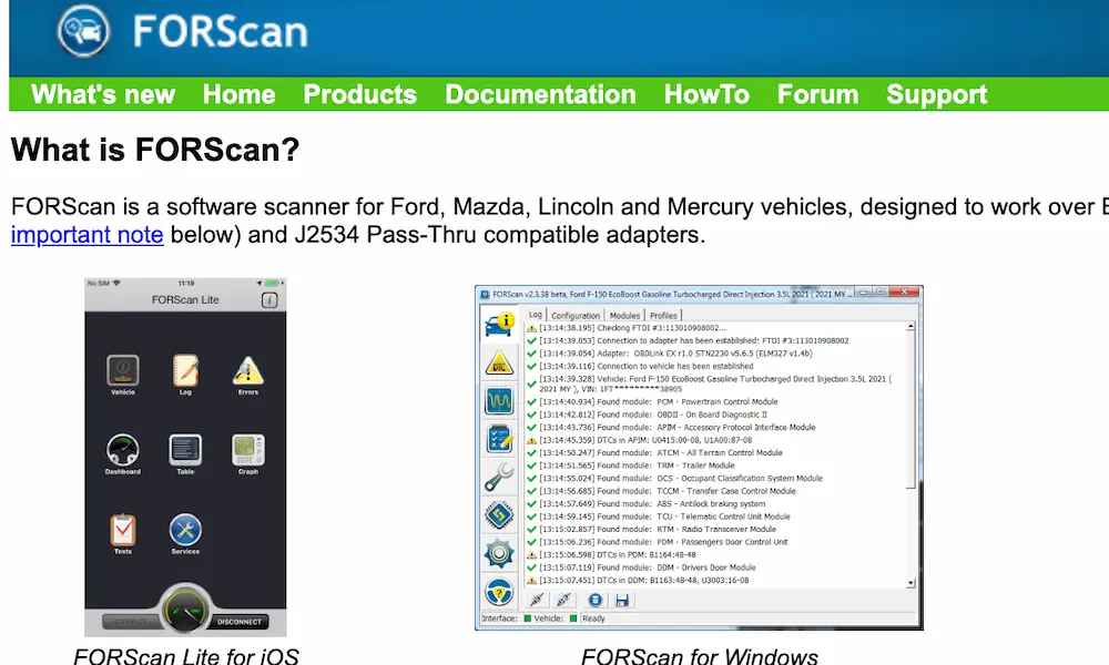
| No overdrive (P0783) | Verify solenoid command with scan tool | Blocked separator plate orifice, wrong gasket, or stuck solenoid regulator valve |
Cooler Line Protocol
Before connecting cooler lines, hot-flush the entire cooling system with a dedicated flush machine. Compressed air alone doesn’t cut it. If the old transmission failed catastrophically, replace the external cooler entirely — fine debris in the cooler passages will destroy your new build fast. Install a magnetic inline filter on the return line to catch any remaining micro-particles.
A proper 4R100 transmission rebuild done with the right upgrades — billet forward drum, 45-element sprag, hardened valve bores, solid bypass nut, and correct clutch clearances — produces a transmission that outperforms the factory unit in every way. Do the job right once, and you won’t be doing it again.