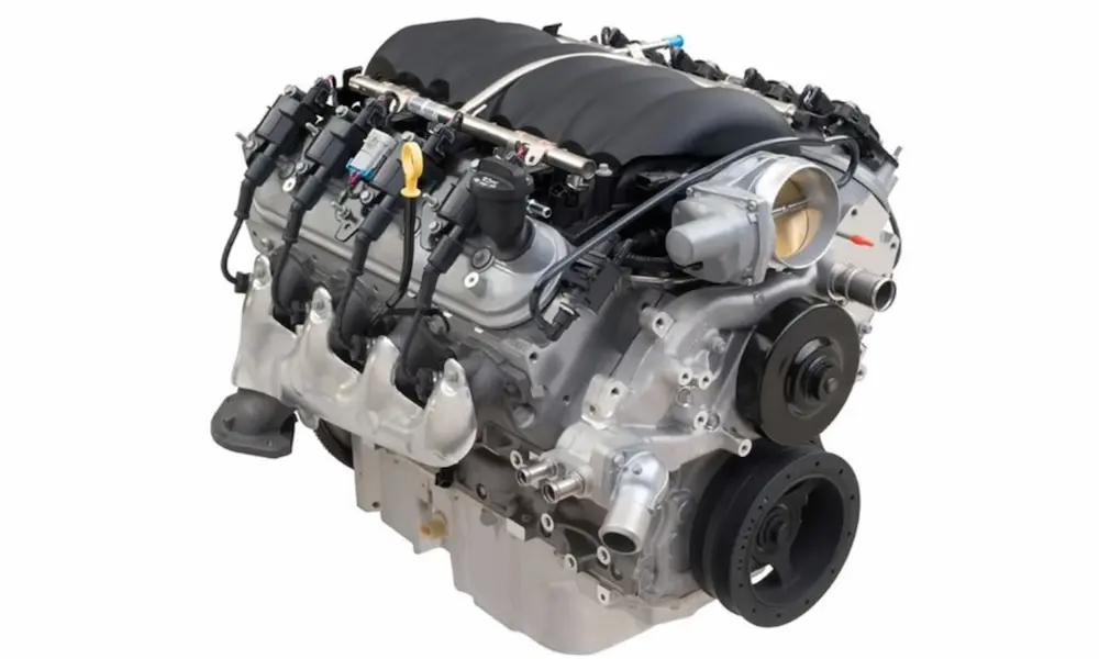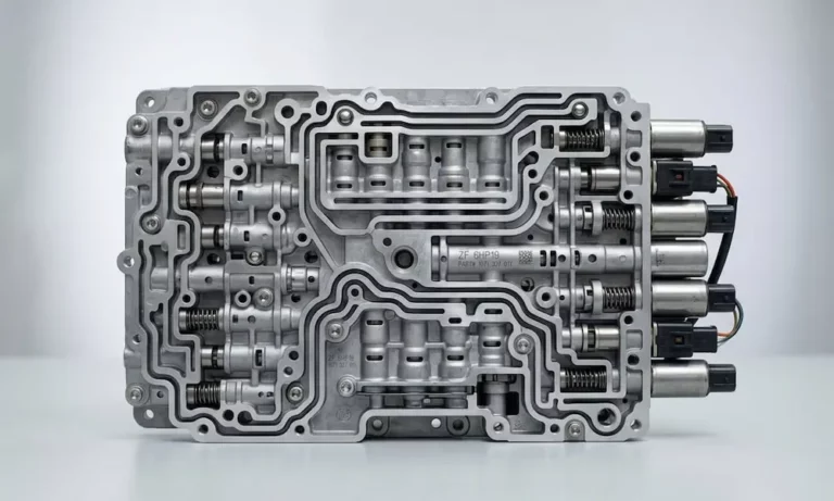
Your Ram is slipping gears, running hot, or banging into shifts like it’s angry at you. Chances are, your 68RFE valve body is the culprit. This guide walks you through everything — symptoms, upgrades, the full replacement process, and the TCM relearn you absolutely can’t skip. Read this before you pull a single bolt.
What the 68RFE Valve Body Actually Does
Think of the valve body as your transmission’s brain and plumbing system rolled into one. It routes pressurized ATF fluid to the right clutch packs at exactly the right moment, controlling every gear change your truck makes.
The 68RFE is fully electronically controlled, meaning the Transmission Control Module (TCM) sends electrical signals to solenoids mounted directly on the valve body. Those solenoids act like tiny switches, moving internal spool valves to direct fluid pressure into specific clutch circuits. When timing is perfect, shifts are smooth and seamless.
The problem? The factory valve body is tuned for comfort and fuel economy — not for towing 20,000 lbs or running an aftermarket tune. Low line pressure settings work fine on an empty highway. Under load, those same low pressures can’t clamp clutches hard enough, and that’s when things get expensive.
Warning Signs Your 68RFE Valve Body Is Failing
Catch these symptoms early and you might save your whole transmission. Wait too long and you’re looking at a full rebuild.
Watch out for:
- Shift flare — engine RPM spikes suddenly without the truck actually accelerating
- Gear slippage — especially noticeable when towing uphill or at wide-open throttle
- Delayed Drive or Reverse engagement — long pause after moving the shifter
- Torque converter shudder — a rumble-strip vibration at highway speeds
- Consistently high transmission fluid temps — a sign clutches are slipping internally
- Limp mode — transmission locks into one gear to prevent total destruction
Common 68RFE transmission problems almost always trace back to the valve body. If you’re seeing two or more of these symptoms together, it’s time to act.
What Actually Goes Wrong Inside the Valve Body
Cross-Leaks and Channel Plate Deflection
The factory channel plate is cast aluminum — soft, and prone to flexing under high hydraulic pressure. The separator plate between the two valve body halves is bare laser-cut steel with zero sealing material.
When pressure spikes during heavy towing or tuning, the aluminum channel plate flexes away from the steel separator plate. Fluid escapes into adjacent circuits. Clutch apply pressure drops. Slippage follows. Heat destroys the fluid and friction material shortly after.
Plastic Accumulator Pistons
The factory accumulator pistons are made of plastic. These components cushion clutch applications by temporarily storing hydraulic fluid. Under repeated thermal cycling and hydraulic shock, plastic warps, cracks, and eventually shatters.
When an accumulator piston fails, fluid vents directly to the sump instead of applying the clutch. The overdrive and underdrive clutches take the worst hit, often resulting in complete loss of higher gears under load.
Solenoid Switch Valve Bore Wear
The Solenoid Switch Valve moves constantly inside a soft aluminum bore. Over time, that bore becomes oval-shaped. Fluid bypasses the valve, routing pressure incorrectly. The result is incorrect pressure routing that triggers limp mode and pressure-related diagnostic trouble codes.
Torque Converter Lock-Up Pressure Loss
When internal sealing degrades, the valve body can’t hold enough pressure to keep the torque converter clutch locked. A slipping torque converter generates massive heat and causes the characteristic shudder at highway speeds. Left uncorrected, the converter eventually fails catastrophically — and sends metal debris through your entire transmission.
Know Your Year: 68RFE Compatibility Differences
Before you buy a replacement valve body, confirm which generation you have. The solenoid pack connector is the easiest identifier:
| Model Year | Solenoid Connector Color |
|---|---|
| 2007.5 – 2011 | White |
| 2012 – 2018 | Gray |
| 2019+ | Blue |
The 2019+ trucks also added a bolt-on transfer plate for the reverse accumulator body. Valve bodies designed for 1999–2018 applications are not cross-compatible with 2019+ transmissions. Also worth checking: if your 2019+ Ram has the Aisin AS69RC transmission instead of the 68RFE, none of this applies — it’s a completely different unit.
Aftermarket Upgrade Options: What Level Do You Need?
Don’t just replace factory parts with factory parts. The engineering fixes are well-established, and the right upgrade depends entirely on how hard you use your truck.
Billet Channel Plate and Bonded Separator Plate
The fix for cross-leaking starts with a billet aluminum channel plate machined from stress-relieved billet stock. It doesn’t flex. Pair that with a bonded separator plate — a steel plate with elastomeric sealing material laminated permanently to it — and every hydraulic circuit seals completely. No more pressure bleeding between worm tracks.
Billet Accumulator Pistons
Trash the plastic pistons. Precision-machined billet aluminum pistons resist distortion under extreme hydraulic shock and typically include redundant sealing rings. Upgraded accumulator springs — often color-coded by circuit — optimize shift feel for specific clutch applications.
Hardened Steel Solenoid Switch Valve Sleeve
The worn aluminum bore gets precision-machined and fitted with a hardened steel sleeve. The valve now rides in steel instead of soft aluminum. Bore wear stops permanently.
Electronic Line Pressure Management
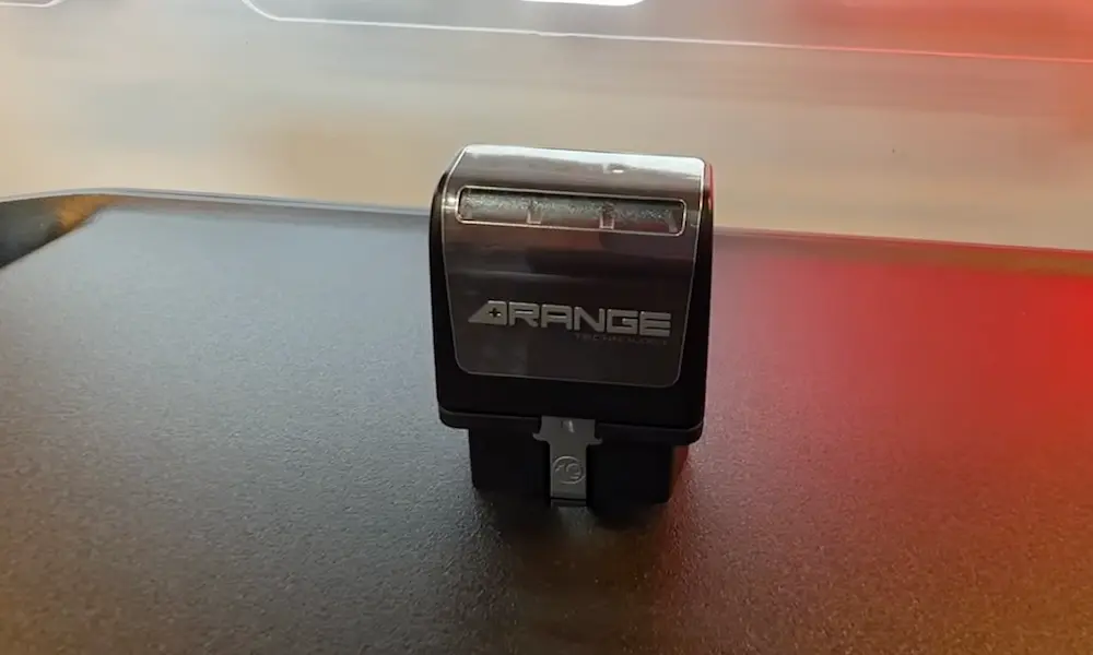
A TCM line pressure booster or electronic co-pilot module intercepts factory pressure signals and commands higher line pressure. This matches clamping force to actual engine output — critical for any tuned truck.
Thermal Management
A deep-sump cast aluminum transmission pan increases fluid capacity and dissipates heat far better than the thin stamped steel factory pan. High-flow external coolers and thermal bypass valves keep fluid in its optimal temperature range.
Choosing the Right Build Level
| Vehicle Condition | Primary Use | Recommended Strategy |
|---|---|---|
| Stock to mild tune | Daily driving, light towing | Performance valve body |
| Tuned (400–500 HP) | Regular towing, spirited driving | Performance valve body + electronic co-pilot |
| High power (500–650+ HP) | Heavy commercial towing, hot tunes | Billet channel plate valve body + co-pilot |
| Max-effort build | Sled pulling, drag racing | Full built transmission + TripleLOK converter |
| Already slipping / burnt fluid | Mechanical failure has occurred | Full rebuild required — valve body alone won’t fix worn clutches |
Before You Start: Check the Fluid First
Pull the transmission pan before ordering anything. The fluid tells you what you’re actually dealing with.
- Dark, burnt-smelling fluid with metallic debris → Hard-part damage has already occurred. A valve body replacement won’t save it.
- Relatively clean fluid with minor friction material suspension → You’re a solid candidate for valve body replacement.
A high-performance valve body is a precision hydraulic instrument. Install it into a transmission already full of metal shavings and you’ll clog the solenoids immediately. Don’t waste the investment.
The Removal Process: Step-by-Step
Work clean. No shop rags inside the transmission — lint kills solenoids. Use only compressed air to dry internal components and only approved transmission parts cleaner for washing.
Step 1 — Fluid Evacuation: Raise the truck safely. Remove the transmission pan and drain the ATF completely.
Step 2 — Filter Removal: Remove the primary sump filter using a T25 Torx driver. Pull the filter down from the pump housing. Unthread and discard the spin-on cooler return filter.
Step 3 — Electrical Disconnection: Carefully unlatch and disconnect the main wiring harness connector from the solenoid pack.
Step 4 — Valve Body Dismounting: Remove the six 10mm hex-head bolts while supporting the valve body from below. It’s heavier than it looks — don’t let it drop.
Step 5 — Extraction: Lower the entire valve body and solenoid pack assembly out of the transmission.
Bench Disassembly and Component Transfer
With the valve body on a clean, well-lit bench:
- Remove solenoid pack bolts and carefully separate the solenoid pack. Wipe electrical components with dry, lint-free material only — never immerse them in cleaner.
- Remove the shift selection assembly, detent spring, and Transmission Range Sensor selector plate.
- Remove the accumulator cover, note every spring and piston location, and install your upgraded billet pistons and performance springs.
- Remove the channel plate fasteners, lift off the channel plate and separator plate, carefully remove all check balls, and document their exact locations.
- Inspect every bore and spool valve for scoring or distortion using a bright penlight. Verify each valve moves freely.
- Clean everything with approved solution, dry thoroughly with compressed air.
- Reinstall check balls in their correct positions, place the new bonded separator plate, then install the upgraded billet channel plate.
Torque Specs and Assembly Sequence
The bonded separator plate has a critical torque sequence that most people get wrong. The channel plate bolts torque to 55 inch-pounds — but in three separate passes with a mandatory 30-minute wait between each pass. The elastomeric sealing material needs time to compress and flow into surface imperfections. Skip the wait and you’ll have cross-leaks within the first drive cycle.
| Component | Torque Spec | Notes |
|---|---|---|
| Channel plate to valve body | 55 in-lbs | 3 passes, 30 min wait between each |
| Solenoid module to transfer plate | 50–55 in-lbs | Start center, work outward |
| Accumulator cover | 40–60 in-lbs | Varies by manufacturer |
| Detent spring | 40 in-lbs | Single fastener |
| Primary fluid filter screw (T25) | 40 in-lbs | Anchors to oil pump |
| Valve body to transmission case | 105 in-lbs | 6 primary fasteners |
| Transmission oil pan | 105 in-lbs | 15 fasteners, alternating pattern |
Before raising the valve body into the case, verify the three valve body-to-case seals are properly seated on top of the assembly. Missing these seals causes immediate massive pressure loss at the pump output.
When installing the new spin-on cooler return filter, strongly consider replacing the factory plastic threaded nipple with an aftermarket metal nipple. The plastic version is notorious for snapping off from vibration fatigue.
Fill with fresh ATF+4 fluid only. Never reuse old fluid. Start the truck in Park, let the transmission reach at least 100°F, then recheck and adjust the fluid level.
TCM Relearn: Don’t Skip This Step
Mechanical installation is only half the job. The 68RFE uses an adaptive learning system built around Clutch Volume Index (CVI) — a calculated value representing exactly how much fluid each clutch circuit needs to complete a shift.
The TCM builds CVI data over thousands of miles, calibrated to your old, worn, leaky valve body. Install a new valve body without resetting this data and the TCM will over-command the tight new circuits, causing violent, harsh shifts.
Do not drive the truck until you complete the Quick Learn procedure.
Connect an advanced scan tool to the diagnostic port. Clear the existing TCM data. Run the Quick Learn procedure from the MISC section of the powertrain software. This cycles the solenoids and establishes new baseline CVI values. Default baseline settings are approximately:
- Low/Reverse clutch: 64
- 2nd clutch: 48
- Overdrive clutch: 89
- Underdrive clutch: 45
After the static Quick Learn, complete a dynamic drive relearn with the transmission fully warmed up. Make 15–20 light-throttle upshifts through all gears. Maintain steady throttle during each shift — lifting the pedal mid-shift aborts the CVI calculation. After reaching 25 mph, perform 5–8 part-throttle kick-downs. No wide-open throttle until shifts feel completely stable.
Normal CVI ranges to verify post-installation:
| Clutch Element | CVI Update Shift | Acceptable CVI Range |
|---|---|---|
| Low / Reverse | 2-1, 3-1, or 4-1 downshift | 45 to 134 |
| 2nd Clutch | 1-2 upshift | 25 to 85 |
| Overdrive | 2-3 upshift | 30 to 100 |
| 4th Clutch | 3-4 upshift | 30 to 85 |
| Underdrive | 4-3 or 4-2 downshift | 30 to 100 |
Values outside these ranges after a completed relearn indicate internal hydraulic issues still present in the transmission.
Frequently Asked Questions
Q: Can electrical problems mimic valve body failure or corrupt transmission data?
Yes. The TCM relies on precise voltage to calculate CVI. A failing alternator or voltage spikes can cause CVI values to drop randomly — even when the truck is cruising steadily in a fixed gear. If CVI values change outside of an active shift sequence, the problem is almost certainly electrical, not hydraulic.
Q: Where do I find CVI data on an aftermarket scan tool, and does it change by year?
It depends on the year. On 2007.5–2009 trucks, CVI data lives in a dedicated TCM. On 2010–2012 models, Chrysler moved this data into the PCM. Tools like the Solus Ultra require navigating to the correct module’s MISC section — it won’t show up in standard live data feeds.
Q: Is it normal for CVI values to drop below the minimum range without indicating a total failure?
Sometimes. The Overdrive clutch occasionally reads near zero without triggering limp mode. If shifts still feel clean with no harsh engagements or delayed responses, low readings alone don’t mean catastrophic failure. But if low CVI readings come with violent shifts or stuck gears, you’ve got serious internal issues — seized accumulator pistons or major cross-leaks.
Q: Why does the transmission need to be warm before the Quick Learn finalizes properly?
Cold ATF is thick. Thick fluid takes longer to fill clutch circuits. The Quick Learn measures the exact time fluid takes to stroke each piston — and cold fluid skews that timing completely. The transmission must reach normal operating temperature (over 100°F) before adaptation produces accurate results.