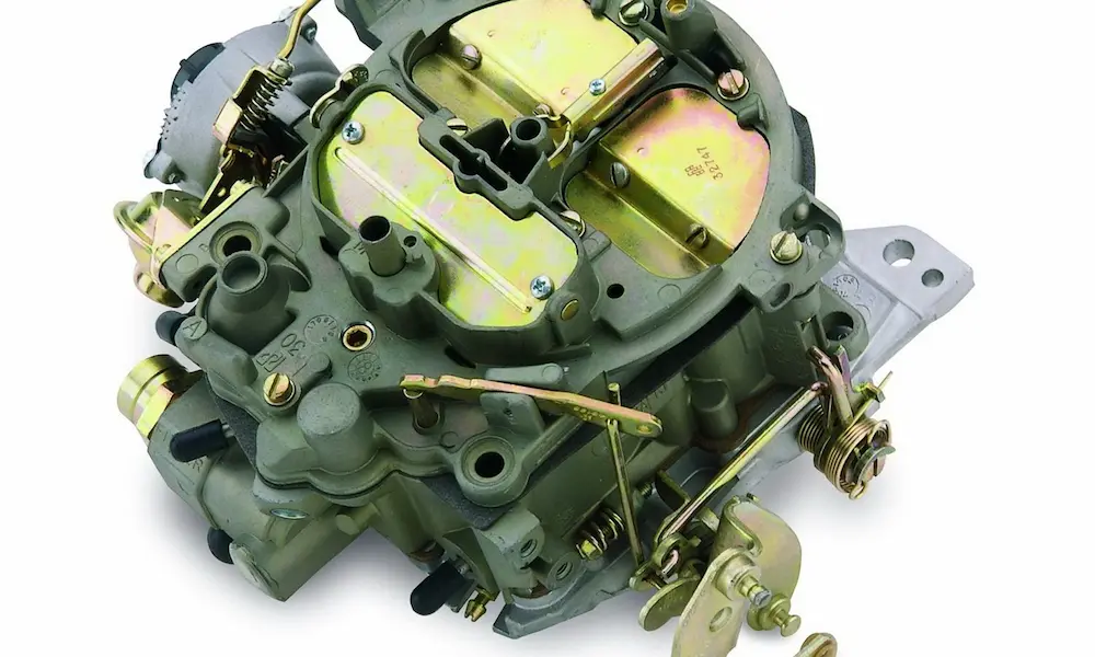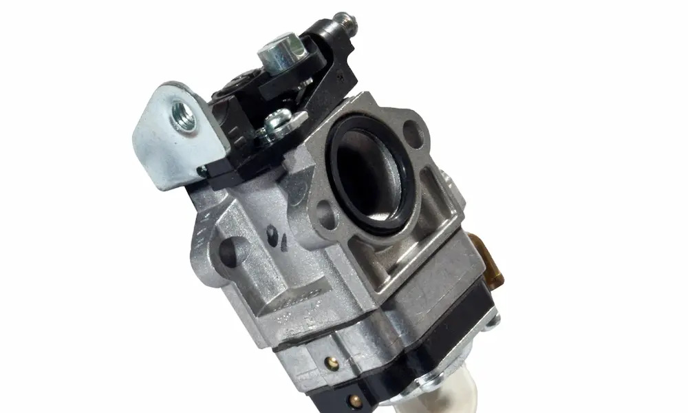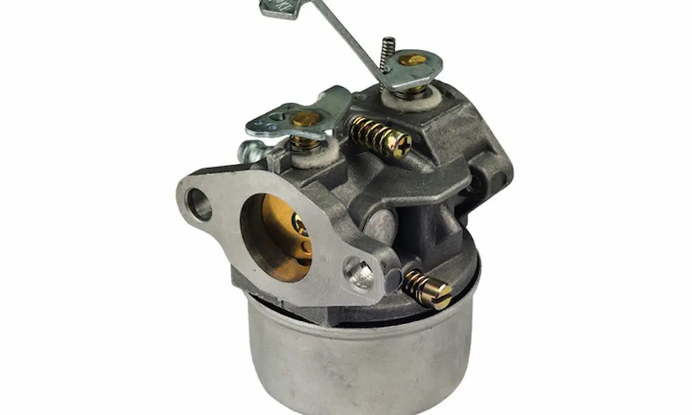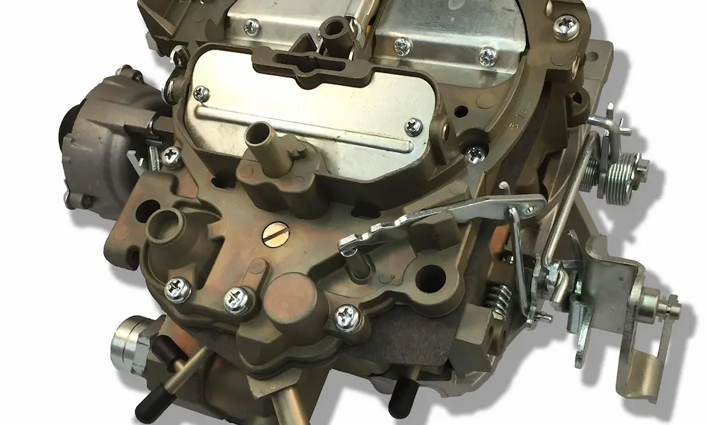
A Mikuni carb diagram looks like a pile of brass confetti. It isn’t. Every part sits where it sits for a reason, and once you know the reason, you can strip your carb, spot a worn piece in seconds, and rebuild it without guessing.
This guide walks the layout for VM, HSR, RS, and CV models. Stick with it and you’ll come away with float heights, jet specs, and the failure points that quietly eat weekends.
What a Mikuni Carb Diagram Actually Shows You
A Mikuni carb diagram is a map of pressure zones. Every part either controls air, controls fuel, or mixes the two.
The exploded view splits into five vertical zones:
- Top cover assembly — seals the slide chamber
- Slide and needle assembly — the moving throttle valve
- Main mixing body — the cast housing holding the venturi bore
- Metering circuitry — jets and needles
- Float bowl assembly — the fuel reservoir
Learn the zones and the parts stop looking random. The needle hangs off the slide. The main jet screws into the bottom of the needle jet. The float bowl feeds all of it.
Why the diagram beats a parts list
A parts list gives you numbers. Jets R Us hosts a full VM exploded view that gives you position, and position tells you what fails together. Leak at the float bowl gasket and fuel hits the outside of the mixing body, not the venturi. The drawing shows you why.
It also shows assembly order. Miss the washer under the needle clip and the needle sits low. Mid-range goes lean. You’ll chase jets for a week.
The Venturi Effect: The Idea Behind Every Mikuni Diagram
Your engine doesn’t suck fuel. Atmospheric pressure pushes it.
That’s the flip most riders miss. The float bowl vents to open air, so the fuel inside sits under normal atmospheric pressure. The venturi — the narrow throat in the carb body — creates a low-pressure pocket as air speeds up through it. The higher pressure in the bowl shoves fuel up the tube and into the stream.
Cycle World breaks the venturi effect down simply. Speed a fluid up, drop its pressure. That’s the whole trick.
Why Mikuni uses a variable venturi
Older carbs ran a fixed venturi with a butterfly valve to choke off flow. Mikuni slide carbs move the slide itself. The slide’s height sets the venturi’s size.
So the air under the slide stays fast even at low rpm. Strong vacuum signal across the whole rev range, and sharper throttle response as a result. Carbiketech digs into the design theory if you want the deeper physics.
Mikuni Carb Diagram by Model Family
Four families cover nearly everything you’ll find in a US garage. Each drawing looks different because each one solves a different problem.
VM Series: The Round Slide Classic
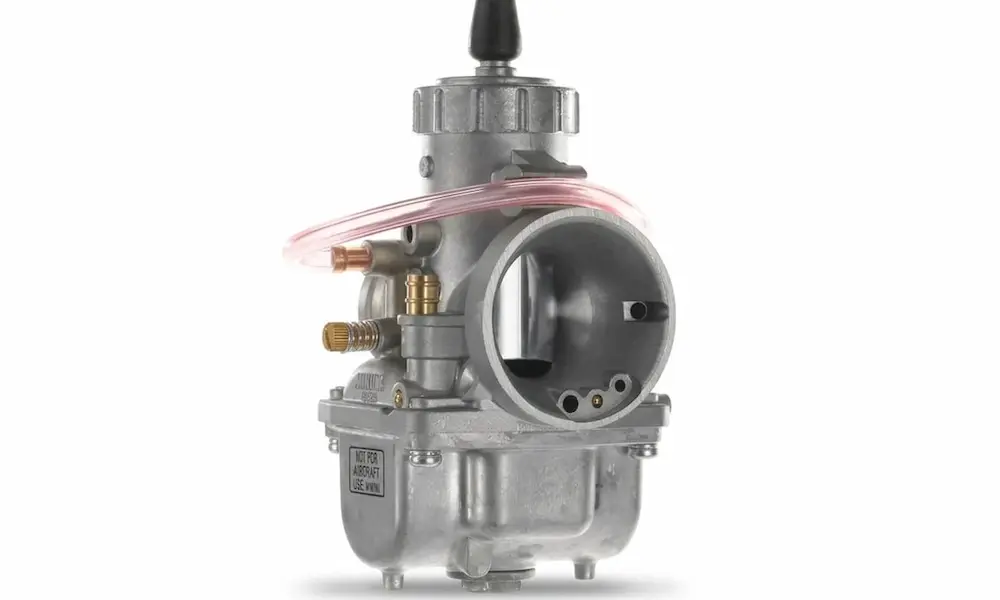
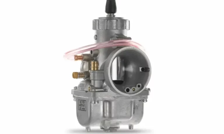
VM carbs are the ones you picture in your head. Cylindrical slide, circular screw-on top cap, no accelerator pump.
Bores run 18mm to 44mm. Mounts come in clamp-on, spigot, and rigid flange. You’ll spot them on vintage Japanese street bikes, two-stroke motocrossers, and snowmobiles.
The layout stays simple. Big spring up top, round slide in the middle, needle jet and main jet stacked in the venturi floor. Mikunioz lists the VM30 internals if you need numbers, and How-To Motorcycle Repair has the printable roundslide diagram.
HSR Series: The Flat Slide for Big Twins
HSR42, HSR45, HSR48. Built for Harley Evolution and Twin Cam motors.
The slide here is flat and rides on eight roller bearings. Why bother? Big V-twins pull monstrous intake vacuum. That vacuum would slam a plain flat slide against the bore and make the throttle feel welded shut. The rollers kill the friction. Light pull, snappy return.
The HSR also runs an accelerator pump. Ian Williams Tuning publishes the official HSR42/45 drawing, and Show and Go covers Harley fitment.
Some HSR setups carry California Air Resources Board compliance when paired with approved intake and exhaust. Worth knowing if you live somewhere with strict smog checks.
RS Series: Radial Flat Slide for Inline Fours
RS carbs ship as synchronized banks — usually four. All four slides lift together through linkage.
Key parts: radial throttle valves, a connector plate tying them together, a bell crank lever, and throttle shafts. One central accelerator pump plunger feeds all four venturis through individual nozzles.
Sync adjustment rings and lock screws hide under the top covers. Orient Express Racing hosts the RS manual.
BS and BST Series: Constant Velocity
CV carbs work on a different principle. Your cable doesn’t lift the slide. It opens a butterfly valve near the engine. The slide hangs off a rubber diaphragm under the top cover and moves on vacuum.
Twist the throttle, vacuum bleeds through holes in the slide bottom, the sealed chamber above the diaphragm evacuates, and atmospheric pressure below pushes the slide up. That’s constant velocity — smooth delivery, no lean bog when you snap the throttle.
CVs show up on multi-cylinder street bikes and big dual-sports. Diaphragms crack with age, so inspect them first.
| Family | Slide Type | Actuation | Best For | Accelerator Pump |
|---|---|---|---|---|
| VM | Round | Cable, direct lift | Vintage street, 2-stroke MX, sleds | No |
| HSR | Flat, roller bearing | Cable, direct lift | Harley Evo/Twin Cam | Yes |
| RS | Radial flat | Cable plus linkage bank | Inline-four street bikes | Yes, shared |
| BS/BST | Diaphragm CV | Vacuum, butterfly on cable | Multi-cylinder street, dual-sport | Varies |
Reading the Circuits on a Mikuni Carb Diagram
A Mikuni carb isn’t one fuel system. It’s five overlapping ones, each owning a slice of throttle. Here’s how the diagram maps to your right hand.
| Throttle | Active Circuit | What You Tune |
|---|---|---|
| Cold start only | Starter enrichment | Starter plunger, starter jets |
| Idle–1/8 | Pilot / idle | Pilot jet, air or fuel screw |
| 1/8–1/4 | Slide cutaway | Throttle valve cutaway number |
| 1/4–3/4 | Jet needle + needle jet | Needle clip position, needle taper |
| 3/4–WOT | Main jet | Main jet size |
| Fast snaps | Accelerator pump | Pump plunger, nozzle |
1. Starter enrichment (cold start)
Mikuni skips the choke plate. It uses a separate fuel-and-air passage controlled by a spring-loaded brass plunger. Lift the plunger and the engine pulls a rich mix straight into the intake.
Critical quirk: leave the throttle closed. Cracking the slide equalizes pressure in the bore and kills the vacuum that drives the circuit. That’s why some bikes actually run worse when you crack the throttle on a cold start. Addlightness walks through the plunger setup.
2. Pilot and idle circuit
At idle the slide is nearly shut. Air speed over the main pickup is too slow to pull fuel. So the pilot circuit feeds from a spot near the engine, where vacuum runs strongest.
The pilot jet sets raw fuel volume. The adjustment screw fine-tunes it. Which screw you have depends on where it sits:
- Air screw (intake bell side, upstream of the slide): turning it in cuts air and richens the mix.
- Fuel screw (manifold side, downstream): turning it in cuts fuel and leans the mix.
Flip those two and every adjustment runs backward. LiteTek’s fuel screw guide sorts out which is which.
Just off idle, small bypass holes behind the slide open up and add fuel. That stops a lean stumble before the needle circuit takes over.
3. Slide cutaway (1/8 to 1/4 throttle)
The arched notch on the bottom of the slide — the air-filter side — is the cutaway. It sets how much air sweeps past the needle jet at small openings.
Bigger number, higher arch, more air, leaner mix. Smaller number, richer mix.
Past quarter throttle, airflow is fast enough that the cutaway stops mattering. The Vintage Bike Builder’s jetting guide covers how the circuits overlap.
4. Jet needle and needle jet (1/4 to 3/4 throttle)
This is where you spend most of your riding, so it matters most.
The needle jet is a brass tube rising into the venturi. The main jet threads into its bottom. The jet needle is the tapered rod hanging from the slide, running down inside that tube. Raise the slide and the needle climbs out, the gap opens, more fuel flows.
Five grooves near the top of the needle set its height:
- Clip lower = needle sits higher = richer.
- Clip higher = needle sits lower = leaner.
Needle jets come in two builds. Primary types have solid walls and suit piston-port two-strokes. Bleed types carry small lateral holes that pre-mix air into the fuel, creating a froth that atomizes better. Four-strokes and reed-valve engines use bleed types.
Sizing runs on a series number for the body (159, 176, 723) plus a letter-number code for the bore (P-4, Q-2, Y-6). Each increment is microscopic. Never poke a needle jet with wire — scratch the bore and you’ve thrown away the calibration. Dan’s Motorcycle Repair explains the needle jet circuit in plain terms.
5. Main jet (3/4 to wide open)
Wide open, the needle’s taper is too thin to restrict anything. The main jet is the only limit left.
Here’s a mistake that costs people real money. Mikuni makes two large main jets that look similar and are not.
| Type | Head Shape | Calibration | Thread |
|---|---|---|---|
| Large Hex (4/042) | Long hex | Flow, cc per minute | M5.3 x 0.9 |
| Large Round (N100.604) | Flat, screwdriver slot | Bore diameter (160 = 1.60mm) | M5.0 x 0.75 |
Different threads. Force one into the wrong needle jet and you strip the brass. Drill Bits Unlimited keeps a jet size chart, and Kawtriple’s jet ID page covers needle jet dimensions.
6. Accelerator pump
Snap the throttle and air rushes in instantly. Fuel is heavier, so it lags. That gap is your bog.
HSR and RS carbs fix it with a mechanical pump. A rod pushes a diaphragm, which squirts raw fuel through a brass nozzle into the throat. That shot covers the lean window until the main circuit catches up. Mike’s Carburetor Parts lists the symptoms of a dying pump.
Float Height: The Number Your Mikuni Carb Diagram Leaves Out
Your diagram shows the float and needle valve. It won’t show you the setting. Get it wrong and every other circuit runs off.
Most people measure with the carb flipped upside down. Don’t. The needle valve hides a tiny spring-loaded pin in its center. Upside down, the float’s own weight compresses that pin and you read a false height.
Use the 45-degree method instead:
- Hold the carb 30 to 45 degrees off horizontal.
- Rotate slowly until the float tang just barely touches the needle pin — no compression.
- Measure vertically from the gasket surface to the top edge of the float.
- Bend the tang gently if it’s off.
| Family | Float Height (±1mm) |
|---|---|
| HSR42/45/48 | 18mm |
| RS Series | 17mm |
| TM32-1, TM34-2, TM36-2 | 18mm |
| TM36-31, TM40-6 | 19mm |
| TMX38-1 | 15mm |
| VM30-83, VM32-193, VM34-168 | 24mm |
| VM36-4, VM38-9, VM40-4 | 18mm |
T-Bolt USA has a walkthrough on adjusting float height if you want photos of the tang.
Failures the Diagram Won’t Warn You About
Three problems eat more Mikuni weekends than anything else.
Flooding and overflow
Fuel pouring from the overflow tubes means the float system failed. Worst case, fuel fills the cylinder and hydro-locks the engine on startup — bent rods, new motor.
Three usual suspects:
- Needle tip hardened or grooved and no longer sealing
- Seat O-ring shrunk or cracked, since ethanol blends chew old rubber fast
- Float developed a pinhole and sank
Test brass floats in hot water. Expanding air pushes bubbles out of any leak. Carburetor Parts covers needle and seat failure.
TMX jet block gasket failure
Late-model KTM and Husqvarna 250/300 two-strokes running the TMX38 have a known gremlin. The engine runs pig rich down low no matter what you change. Plug fouling, burbling, no clean pull.
It’s the jet block gasket. It warps and fails, dumping unmetered fuel straight into the venturi past the pilot and needle circuits. The gasket often isn’t listed on OEM parts fiches, so people buy whole new carbs. Rutherford Racing sells a proper repair kit with a thicker, fuel-resistant gasket. Cheap fix for a nasty symptom.
Snapped pilot mixture screw
Brass screw, aluminum seat, heavy hand. Snap the tip off inside the pilot circuit and your idle is plugged.
Don’t drill it. A steel bit will wallow out the soft aluminum orifice and the carb never meters right again. Instead, look down through the venturi for the tiny hole where the tip pokes through. Use a sharp awl or a needle in vise-grips, press gently downward, and push the tip backward out the threaded channel. Heat or cold shock first helps break the friction fit. There’s a solid write-up on the extraction method.
Final Thoughts
A mikuni carb diagram stops being intimidating once you know the zones. Top cover, slide, mixing body, metering circuits, float bowl. Five areas, each with one job.
Then stack the circuits on top by throttle position. Pilot for idle, cutaway for the transition, needle for mid-range, main jet for wide open, pump for snaps. Now a symptom points at one small area instead of the whole carb.
Grab the right diagram for your model family and print it. Keep your float height honest, watch for the gasket and O-ring failures ethanol accelerates, and leave the drill bit in the drawer when a brass screw snaps. That’s most of what separates a carb that fights you from one that just works.