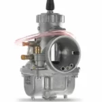
A Honda GCV160 carb diagram looks simple — until you’re standing there holding six gaskets and no clue which way they face. This guide walks the whole fuel system, from the float bowl to the governor linkage. You’ll learn what each hole and passage actually does, how to pull the carburetor apart, and how to stop that surging that brought you here. Stick with it to the end and you’ll reassemble it right the first time.
What a Honda GCV160 Carb Diagram Actually Shows
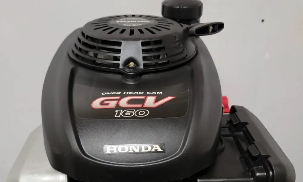
The diagram maps a small but busy machine. The GCV160 displaces 160 cc (9.8 cubic inches) and puts out 4.4 horsepower at 3,600 rpm, with 6.94 pound-feet of torque at 2,500 rpm. You’ll find it on walk-behind mowers, pressure washers, tillers, and small generators, and it meets US emissions rules without a catalytic converter. You can check the full engine specs or read Honda’s own model page for the launch details.
The engine uses an overhead cam, a timing belt, a vertical crankshaft, and a uniblock casting that combines the cylinder and head into one aluminum piece.
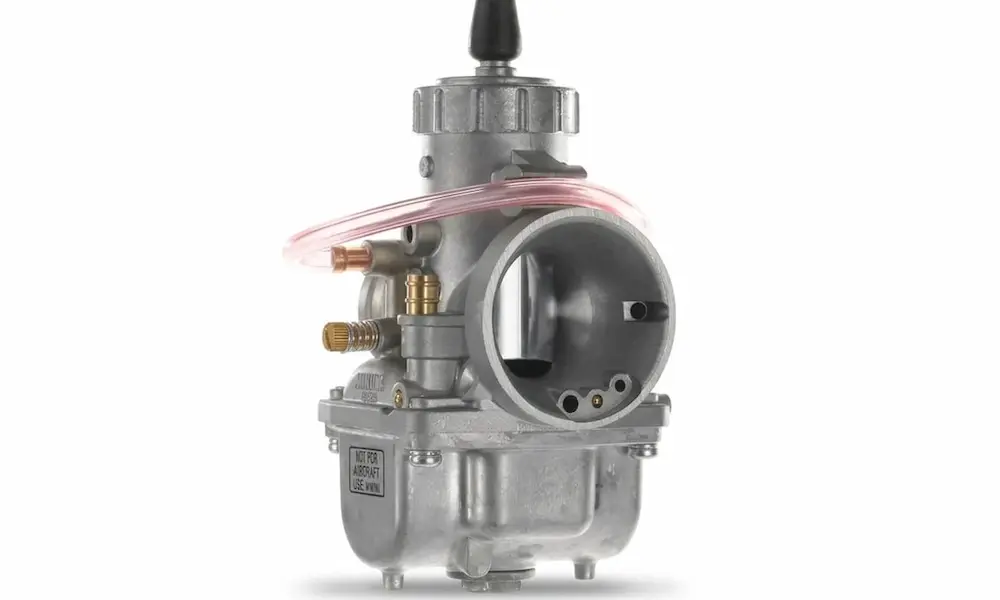
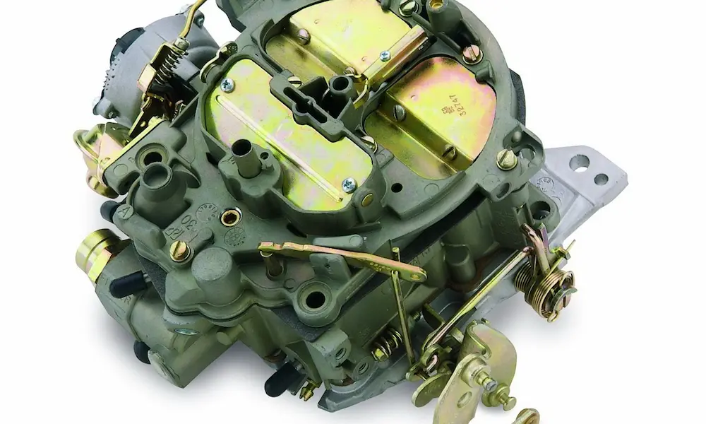
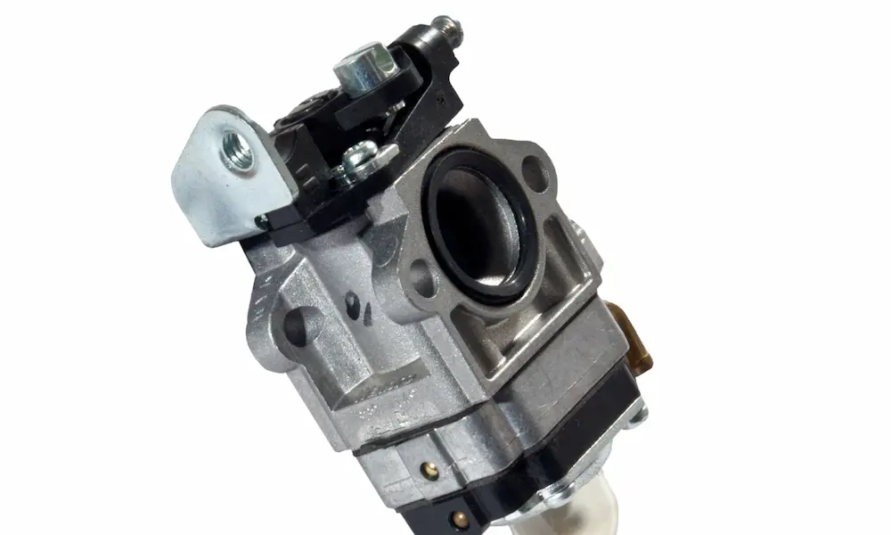
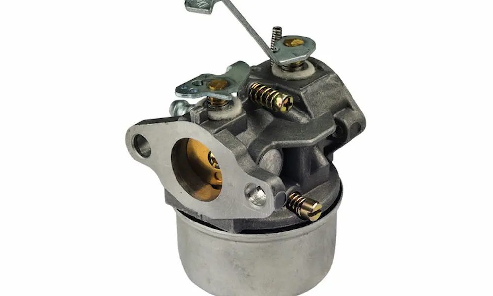
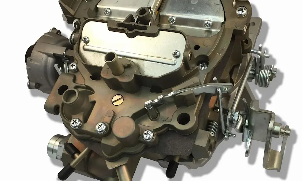
The carb itself is a horizontal butterfly-valve design. It works on the venturi principle. When the piston drops, it pulls a vacuum. Air rushes through a narrow throat and speeds up. That speed drop in pressure siphons fuel up through tiny brass jets and turns it into a mist the engine can burn.
| Spec | Number |
|---|---|
| Displacement | 160 cc / 9.8 cu in |
| Peak power | 4.4 hp @ 3,600 rpm |
| Peak torque | 6.94 lb-ft @ 2,500 rpm |
| Idle speed | 1,700 ± 150 rpm |
| Max speed (no load) | 3,100 ± 150 rpm |
Match the Diagram to Your Carburetor First
Honda built the GCV160 for a lot of different machines, so the carb must hook up to several control setups. Honda’s own paperwork lists up to nine control types, sorted by how the choke, throttle, and brake work.
Mowers with a blade brake clutch or flywheel brake often run a fixed throttle plate. The engine holds one speed, and you only control spark and choke. Pressure washers and tillers usually get an adjustable throttle, so you can change governed speed with a cable or a lever.
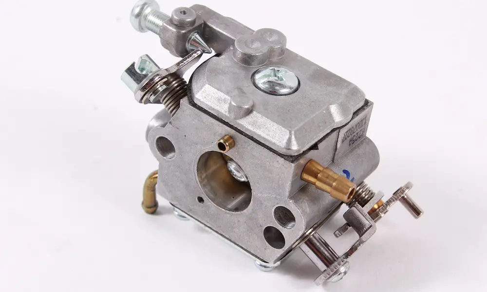
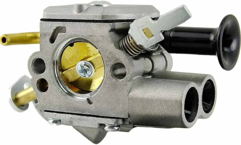
Because of that, Honda made several carb iterations. Find the alphanumeric code stamped on the side of the aluminum body. Common families include BB75, BB76A, and BB76B, plus OEM part numbers like 16100-Z0L-023, 16100-Z8B-901, and 16100-Z0L-853. Your engine manual lists which one fits your model.
Grab the wrong one and you’ll fight it. Bolting a fixed-throttle carb onto a variable-throttle pressure washer causes serious linkage problems and governing failures. A standard replacement assembly ships with the main body, throttle and choke butterflies, the emulsion tube, main jet, pilot jet, float, and float valve — all set to factory spec. You can see the exploded carburetor parts breakdown to confirm what you’re ordering.
Part 1: The Float Bowl
The float bowl sits at the bottom of the carb. It’s the small fuel tank the carb drinks from while the engine runs. A custom rubber ring seals it to the aluminum body — 51 mm outside diameter, 47.5 mm inside, and 1.6 mm thick.
Inside, a hinged plastic float rides on the gasoline. Fuel flows in from the gravity-fed tank, the level rises, and the float lifts. A rubber-tipped needle valve rides on that hinge. Once the fuel hits exactly 9.2 mm, the float presses the tip into a brass seat and shuts off the flow. As the engine burns fuel, the level drops, the valve opens, and the cycle repeats. That’s the whole balancing act.
Why Ethanol Gas Kills the Float System
Modern ethanol-blended gas is rough on this setup. Store your mower for months and the volatile compounds evaporate, leaving a sticky varnish behind. That varnish gums up the float hinge and the needle tip.
If the needle sticks closed, the engine fires on the leftover bowl fuel and then dies of starvation. If it sticks open, or a speck of debris jams the tip, fuel floods in without stopping. Raw gas then pours out the atmospheric vents or runs down the intake, past the valve, and into the cylinder — where it thins your oil and can wreck the engine from the inside.
The Drain Screw Rule You Shouldn’t Skip
The bowl has a drain bolt at its base. Honda is blunt about this: if you’re storing the engine more than three months, shut off the main fuel valve and loosen that bolt to empty the bowl. Or just run the engine until it stalls. Same result.
When you put the bowl back on, face the drain bolt outward. That way you can reach it with a normal screwdriver without fighting the cylinder block or the mower deck. There’s a handy explanation of drain screw placement if yours looks ambiguous.
Part 2: Main Jet and Emulsion Tube
Fuel leaves the bowl through the carb’s central column. At the very bottom of that column, sitting in the liquid gas, is the main jet — a threaded brass restrictor with a microscopic hole drilled through the center. That hole sets the maximum fuel the engine can drink at full load and high rpm.
Because air thins out as you climb, the GCV160 takes different jets. Near sea level, you want the standard size — typically a number 60 or 65. Up high, where oxygen density drops, a smaller number 55 or 58 keeps the air-fuel ratio in range. Run a sea-level jet at altitude and you’ll get black smoke, a fouled plug, and weak power. Honda’s official carburetor check sheet spells out the sizes.
What the Emulsion Tube Adds
Right above the main jet sits the emulsion tube, also called the main nozzle. It’s a hollow brass cylinder drilled with tiny cross-holes. Air leaks in through those holes as fuel climbs the column, turning solid liquid into a frothy, aerated mix.
That matters more than it sounds. Liquid gasoline doesn’t burn well — only vapor does. When the frothy emulsion hits the fast-moving air in the venturi, it shatters into a fine mist. Clog those cross-holes with varnish and you get a solid stream of liquid instead. The result: rough high-speed running, incomplete burns, and lousy emissions.
To clean it, pull the bowl, back out the main jet with a properly sized flathead, and let the emulsion tube drop free. Then clear both with the right probe — the 0.5 mm wire in Honda’s official cleaning kit (Needle A). Need a walkthrough? This step-by-step carburetor removal video shows the sequence, and this forum thread on pulling the jet covers the stubborn cases.
Part 3: The Pilot Circuit
The main jet does almost nothing at idle. When the throttle plate sits nearly closed, vacuum in the venturi collapses, so heavy fuel can’t climb the main column. The engine leans entirely on a second path: the pilot circuit.
The pilot jet lives at the top of the carb body, separated from the bowl assembly. On some GCV160 versions it’s a removable brass piece. On others it hides beneath the idle speed screw, often under a black plastic cap.
Here’s the problem. Your idle only needs 1,700 rpm worth of fuel, so the pilot orifice is unbelievably small. That makes it the most fragile part of the whole system. A flake of rust or a whisper of fuel varnish shuts it down completely, as plenty of owners discover.
Spotting a Clogged Pilot Jet
The tell is specific. The engine only runs when you hold the choke on. By blocking air, the choke forces a deep vacuum that drags fuel from the main circuit, covering for the dead pilot passage. At partial clog, you’ll get a wild idle that swings up and down.
Cleaning takes a delicate hand. Use the 0.3 mm wire probe (Needle B) from the Honda kit. Welding tip cleaners or oversized bits will scratch the soft brass or wallow out the hole, and that carburetor is done — permanently. Learn the carburetor maintenance procedure before you touch it.
The pilot screw fine-tunes the mixture, and US emissions rules mean Honda seals it with a plastic limiter cap. That cap blocks you from turning the screw more than a fraction, keeping the engine out of a rich, high-emission state. If the passages behind it clog, the official repair calls for snapping the screw’s narrow neck to remove the cap, extracting the threaded stub with a rubber friction tube, and replacing the whole assembly. Seat the new screw, back it out to the manual’s depth, then bond a fresh limiter cap with LOCTITE 638.
Part 4: The Gasket Stack — Get This Right
Here’s where most GCV160 repairs go wrong. The carburetor, the plastic thermal insulator, and the air filter housing all clamp together under two long bolts that thread into the cylinder block. Pull those bolts and nothing holds the inner parts together. Everything falls apart in a pile.
The insulator exists for a reason. The uniblock head runs scorching hot, and aluminum conducts heat fast. Bolt the carb straight to it and the fuel in the bowl boils. Those vapor bubbles — vapor lock — wreck the venturi vacuum and stall the engine until it cools. Honda fixes that with a thick, hard plastic thermal break and a strict gasket order.
Going outward from the bare engine face:
| Position | Component | Job |
|---|---|---|
| 1 (engine side) | Intake port gasket | Seals the block to the insulator |
| 2 | Thermal insulator spacer | Blocks heat transfer |
| 3 | Air guide gasket | Seals insulator to carb |
| 4 | Carburetor assembly | Meters the fuel |
| 5 | Carburetor intake gasket | Seals carb to air box |
| 6 (outboard) | Air filter housing base | Holds the filter, routes air in |
A few early builds added a thin metal air guide plate between the insulator and the air guide gasket. Later versions dropped it. You can see the insulator and gasket set layout if your engine has that extra plate. This forum discussion on gasket order covers the confusing variants.
Orientation and the Vent Holes
The mating faces carry more than a big bore and two bolt holes. They also have tiny off-center channels that vent the float bowl to atmosphere. The carb needs constant air pressure pushing down on the fuel inside — that pressure is what lets the venturi vacuum pull fuel up the main jet.
The gaskets and insulator have matched cutouts for those vents. Flip one backward or upside down and solid paper blinds the passage. Now the bowl pressure equalizes with venturi vacuum, the pressure differential vanishes, and the engine starves. Worse, heat expansion in an unvented bowl can shove raw gas past the needle valve and flood the cylinder.
The Guide-Stud Trick
Six loose pieces are a nightmare to balance. Pros cheat. Thread two long headless studs into the block, then slide the gasket, insulator, gasket, carb, gasket, and air box onto them in order. Everything stays parallel, so you can eyeball the stack and confirm no gasket slipped over a vent hole. Then swap the studs for the real bolts one at a time, torqued to 10 Nm. This video on gasket sequence shows how smoothly it goes.
Part 5: The Auto Choke and Thermowax
Many GCV160s skip the manual choke lever entirely. The Auto Choke system handles it, and the heart of it is the thermowax plunger.
A spring holds the choke butterfly closed whenever the engine is off. That closed plate chokes off air and pulls a rich fuel charge for a cold start — one pull, usually. But leave the choke closed after ignition and you get black smoke, a carbon-fouled plug, and stalling.
The thermowax fixes that. It’s a small brass cartridge threaded into a blind cavity in the cylinder barrel. Inside sits a wax compound that expands hard when heated. As the cylinder warms, heat soaks through the aluminum into the brass. The expanding wax pushes a rubber diaphragm, which drives a metal pin outward. That pin presses the auto-choke linkage and swings the choke plate wide open. Full warm-up takes about two minutes.
When Thermowax Fails
Thermal cycling degrades the wax and can rupture the diaphragm. The pin then stops extending, and the choke sticks shut forever. The giveaway: starts great cold, runs awful hot — dark smoke, no power. You can find thermowax replacement details in the official auto-choke repair guide.
Part numbers include 16620-Z9L-003 and 16620-Z8D-842. Check whether your engine has a square or round intake port — the linkage geometry differs. You can match the part through OEM thermowax listings.
Before installing, measure the new unit at room temperature. It must fall between 21.5 and 23.0 mm. Longer than 23 mm and it’ll hold the choke open on cold starts. Outside tolerance, toss it.
Old cartridges seize into the cavity. The manual’s trick: drive a number six sheet metal screw into the old body and pry it out using the valve cover edge for leverage. Clean the cavity with compressed air. Then coat the lower third of the new brass cartridge with Hondabond HT or Loctite 5900. That high-temp sealant holds the part against vibration and acts as a thermal bridge, so heat reaches the wax core fast. Press it home, fit the linkage over the pin, and bolt it up.
Part 6: The Centrifugal Governor
You never control the throttle butterfly directly. The engine does it for you, using a centrifugal governor buried in the crankcase. The goal: hold a steady speed no matter the load.
Hit thick wet grass and rpm drops. Heavy metal weights spinning on a camshaft-driven gear lose outward force and collapse inward, rotating a shaft that pokes through the block. The outside governor arm swings, tugging a thin rod on the carburetor. The butterfly opens wide, more air and fuel rush in, and power returns. Load drops, rpm spikes, weights fly out, throttle closes. That’s the loop.
A friction clamp ties the internal weights to the external arm. Years of vibration — or aggressive yanking during a repair — makes it slip. Then the engine either won’t open the throttle under load or holds it wide open and over-revs. Honda’s engine adjustment bulletin is the authority here, but the sequence is:
- Engine cold and off. Loosen the governor clamp nut.
- Push the arm so the throttle linkage hits full wide open.
- Hold it there, grab the bare shaft with pliers, and turn it fully clockwise to its hard stop.
- Tighten the clamp nut to 10 Nm with both held in place.
Baseline speed then comes from the governor spring. Bend its anchor tab to raise or lower max rpm. Idle speed comes from the throttle stop screw on the carb.
| Parameter | Spec |
|---|---|
| Standard idle | 1,700 ± 150 rpm |
| Max speed (no load) | 3,100 ± 150 rpm |
| Flywheel brake / EU variants | 2,900–3,000 rpm |
There’s a quick governor setup demonstration and a longer governor adjustment thread if you want to see it done.
Fixing Surging and Hunting
Surging is the number one GCV160 complaint. Speed dives like it’s about to die, then roars back to full, over and over. It’s almost always a lean mixture — too much air, too little fuel.
The governor turns a weak burn into a rhythm:
- The lean charge burns poorly, so rpm drops fast.
- The governor sees the drop and snaps the throttle wide open.
- That burst of air and fuel fires hard, spiking the speed.
- The governor slams the throttle shut to save the engine.
- The lean condition starves it again, and the cycle loops forever.
Two root causes produce that lean state.
A blocked pilot circuit. Gummed fuel varnish chokes the tiny idle passages. Test it: pull partial choke while it’s surging. If the idle smooths out instantly, you’ve confirmed fuel starvation — the choke is covering for a clogged jet. Clean the passages and it’s fixed.
An intake vacuum leak. If you’ve cleaned or replaced the carb and it still surges, unmetered air is sneaking in behind it. Culprits are the usual suspects: a backward thermal insulator, a warped one, or under-torqued bolts leaving a hairline gap. Owners hit this constantly, even with brand new carburetors installed.
To find the leak, run the engine while it surges and spray short bursts of carb cleaner at the joints between the block, the insulator, and the carb base. When the vapor gets sucked into a bad gasket gap, the extra fuel corrects the mixture and the engine evens out. The exact spot where the surging stops is your leak.
Don’t Forget Valves and Spark
The carb only meters fuel. The piston’s downstroke creates the vacuum that pulls it through, and that depends on the intake and exhaust valves sealing tight against the uniblock head. A too-tight intake valve bleeds compression back out through the carb. A too-loose one won’t open far enough to build real vacuum. Any serious fuel system diagnosis should include a valve lash check.
Set clearances cold, with the piston at top dead center on the compression stroke. Line up the stamped marks on the camshaft pulley parallel with the head cover surface.
| Valve | Clearance | Lock nut |
|---|---|---|
| Intake | 0.15 ± 0.04 mm | 8 Nm |
| Exhaust | 0.20 ± 0.04 mm | 8 Nm |
On the ignition side, Honda specifies an NGK BPR6ES plug, gapped to 0.7–0.8 mm and torqued to 20 Nm. The coil itself needs 0.2–0.6 mm of air gap from the flywheel magnets, set with a long feeler gauge. Miss that and the spark lands at the wrong moment, wasting the fuel your carb just metered so carefully.
Torque Specs Cheat Sheet
Over-tightening is the classic amateur move. It crushes paper gaskets, cracks the plastic insulator, and warps the cast aluminum carb body — instant vacuum leaks you can’t undo. Under-tightening lets vibration shake everything loose. Stick to these numbers.
| Hardware | Nm | ft-lb |
|---|---|---|
| Air cleaner case bolts (carb mount) | 10 | 7.0 |
| Governor arm clamp nut | 10 | 7.0 |
| Valve adjusting lock nut | 8 | 5.8 |
| Cylinder head cover bolts | 12 | 8.6 |
| Standard 6 mm hardware | 10 | 7.0 |
| Standard 5 mm hardware | 5.5 | 4.0 |
These limits compress the gasket stack properly — a clean seal across the venturi without crushing fibers or blocking those vital bowl vents.
Final Thoughts
A Honda GCV160 carb diagram isn’t just a map of parts. It’s a snapshot of a system where atmospheric pressure, heat management, gasket layering, and governor balance all have to line up at once. Change one and the rest complain.
So work in order. Identify your carb code before buying anything. Clear jets with the right probe size, never a drill bit. Face the insulator and gaskets the correct way, and use guide studs to keep the stack honest. Calibrate the thermowax length and the governor linkage exactly as specified. Then, when the surging starts, you’ll know whether you’re chasing a blocked pilot jet or a hidden vacuum leak — and you’ll fix it in one pass instead of three. Do that and your GCV160 will keep delivering the quiet, clean, reliable power Honda built into it.