
Is your Ford dashboard showing strange warning lights? Are electronic systems acting up? If your mechanic mentioned the Ford B1318 code, you’re dealing with a low battery voltage issue. This isn’t just about a dying battery—it’s a symptom that could point to several electrical problems in your vehicle. I’ll walk you through everything you need to know about this common Ford diagnostic trouble code.
What Does Ford B1318 Code Mean?
The B1318 code in Ford vehicles specifically indicates “Battery Voltage Low.” When your car’s computer (either the Powertrain Control Module or Driver Seat Module) detects that battery voltage has dropped below the minimum threshold, it triggers this code.
For most Ford systems, the alarm bells start ringing when voltage falls below 11 volts for a sustained period. In some specific systems like the 4X4 control module, the threshold is even lower—around 9 volts for at least 10 seconds while the engine is running.
Think of B1318 as your car’s way of saying, “I’m not getting enough electrical power to function properly!” This code is Ford’s early warning system, alerting you before more serious electrical failures occur.
Common Symptoms When B1318 Appears
When your Ford develops a B1318 code, you’ll likely notice several telltale signs:
- Illuminated battery warning light on your dashboard
- Radio producing distorted sound (like “someone singing with marbles in their mouth”)
- Multiple electronic systems malfunctioning simultaneously
- Start-stop system refusing to operate
- Erratic behavior from power windows, locks, or other accessories
- Difficulty starting the vehicle, especially after sitting overnight
One interesting pattern is how this code can affect multiple systems at once. Some drivers report B1318 codes appearing in their Anti-Lock Brake System, Airbag System, GEM-Control Timer, and Instrument Cluster all at the same time—showing how a voltage issue can cascade throughout the vehicle.
What Causes the B1318 Code?
1. Failing Alternator or Charging System
The most common culprit behind the B1318 code is a failing alternator or charging system. Ford vehicles use PCM-controlled alternators that should maintain voltage between 13.8-14.8 volts while the engine runs. When the alternator fails or the communication between it and the PCM breaks down, voltage drops below acceptable levels.
An interesting case involved a 2006 F-350 where mice had chewed through the charging system wiring. Despite having a new alternator and batteries installed, the damaged wiring prevented proper communication between the PCM and alternator, triggering the B1318 code.
2. Battery Deterioration
As batteries age, their internal resistance increases and capacity decreases. Ford’s Battery Management System (BMS) aims to maintain batteries at 75-80% state of charge during normal operation. When a battery deteriorates beyond its ability to hold this charge level, the B1318 code appears.
A fully charged battery should measure approximately 12.4-12.8 volts at rest. Different Ford models have specific expectations—Lariat models with 800 CCA batteries should read around 12.89 volts at 100% charge, while XL/XLT models with 720 CCA batteries should read about 12.76 volts.
3. Parasitic Electrical Drains
Excessive current draw when the vehicle is off can trigger B1318 codes. Ford recommends total key-off current consumption should not exceed 100mA. According to Ford’s BMS documentation, the system requires rest periods of at least 4 hours with less than 100mA current draw to properly calibrate.
Aftermarket accessories, damaged wiring, or failed control modules can create parasitic drains that exceed this threshold and prevent proper BMS calibration.
4. Corroded or Damaged Connections
Poor connections at battery terminals, damaged ground straps, or corroded wiring harnesses often cause B1318 codes by creating voltage drops in the electrical system. Since Ford’s charging system monitors voltage at multiple points, different readings at these points can confuse the control modules and trigger false codes.
How to Diagnose the B1318 Code
Basic Voltage Testing
Start with these simple measurements using a digital multimeter:
| Test Condition | Expected Voltage | What It Means |
|---|---|---|
| Engine off | 12.4-12.8V | Healthy battery charge |
| Engine running (idle) | 13.8-14.8V | Normal charging system operation |
| During acceleration | 12.2-12.8V | Normal temporary drop as system optimizes power |
| Battery at 100% charge (Lariat) | 12.89V | Specific to 800 CCA batteries |
| Battery at 100% charge (XL/XLT) | 12.76V | Specific to 720 CCA batteries |
Remember that Ford’s smart charging systems use variable voltage depending on driving conditions. During acceleration, voltage may temporarily drop to 12.2-12.8 volts as the system allows the battery to supply electrical loads while preparing for regenerative charging during deceleration.
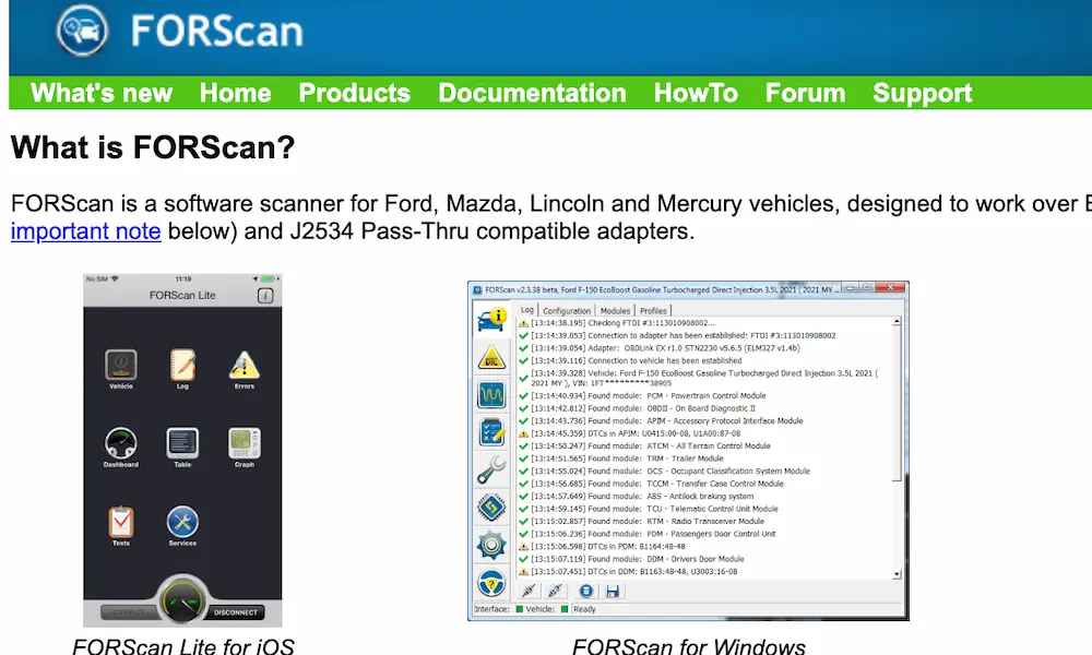
Scan for Multiple Codes
Use an OBD-II scanner to check all vehicle modules for the B1318 code and related fault codes. The code may appear in multiple modules simultaneously, indicating a system-wide voltage problem rather than an isolated component failure.
Look for related codes such as P1000 (OBD monitor incomplete), which often accompanies B1318 after battery disconnection or replacement.
Test for Parasitic Draw
To check for excessive parasitic draw:
- Disconnect the negative battery terminal
- Set your multimeter to read DC amps
- Connect the multimeter between the negative battery post and the disconnected cable
- Wait for all modules to go to sleep (typically 30 minutes)
- The reading should be less than 100mA
- Remove fuses one by one to isolate the source if current is excessive
Advanced Alternator Testing
For vehicles with PCM-controlled alternators, specialized testing involves monitoring the GENCOM (generator command) and GENMON (generator monitor) circuits. The PCM sends pulsing ground signals to control alternator output, and the alternator returns feedback signals indicating actual load.
Using a scope to monitor these signals can reveal communication problems between the PCM and alternator that cause charging system failure and B1318 codes.
How to Fix the B1318 Code
Alternator and Charging System Repairs
When charging system problems cause B1318, repairs typically involve alternator replacement or wiring harness repair. Ford’s 6G series alternators use small gauge wires that are prone to breaking inside the insulation, causing intermittent no-charge conditions.
For damaged charging system wiring, Ford provides specific pigtail repair kits. The part number WPT-1045 or 1U2Z-14S411-AHC covers common alternator connector repairs. According to electrical rebuilder documentation, proper repair involves carefully splicing the new connector while maintaining correct wire positions and routing.
Battery Replacement and Programming
When replacing the battery, pay attention to Ford’s Battery Management System requirements. The BMS must be properly calibrated to recognize the new battery specifications.
Important considerations for battery replacement:
- Connect battery chargers on the correct side of the current sensor to ensure the BMS accurately monitors charging current
- For older BMS systems, the current sensor wraps around the negative battery cable, requiring charger connections downstream of this sensor
- Newer integrated systems require charger connections at specific points to ensure proper current monitoring and BMS calibration
Clean and Secure Connections
Sometimes the fix is as simple as cleaning and securing electrical connections:
- Remove both battery terminals and clean them with a wire brush
- Clean the battery posts thoroughly
- Inspect and clean ground connections to the chassis and engine
- Apply a light coating of dielectric grease to prevent future corrosion
- Tighten all connections to manufacturer specifications
PCM Memory Reset Procedures
After repairs, clear PCM adaptive memory to eliminate learned compensation values that may have developed due to the low voltage condition:
- Disconnect both battery terminals
- Create a jumper between the positive terminal and vehicle ground for 5-10 minutes to discharge PCM capacitors
- Reconnect the battery
- Perform a relearning drive cycle where the transmission shifts through all gears under light acceleration
This process allows the PCM to establish new baseline values without the influence of previous low-voltage adaptations.
Preventing Future B1318 Codes
To avoid future B1318 troubles, implement these preventive measures:
- Regular Battery Testing: Have your battery load-tested every 6-12 months, especially before extreme weather seasons.
- Inspect Charging System: During routine maintenance, verify alternator output (13.8-14.8V) and check belt condition.
- Limit Aftermarket Accessories: Ensure any added electronics don’t create excessive parasitic draw. The total should remain below Ford’s 100mA threshold.
- Allow BMS Calibration Time: Periodically allow your vehicle to sit undisturbed for at least 4 hours to let the Battery Management System complete its calibration cycle.
- Keep Connections Clean: Apply terminal protector spray and check for corrosion during seasonal maintenance.
- Drive Regularly: Short trips don’t allow sufficient charging time. Occasional longer drives help maintain battery health.
- Consider a Battery Tender: For vehicles that sit for extended periods, a quality battery maintainer can prevent voltage depletion.
The Complexity of Modern Ford Electrical Systems
Ford’s modern electrical architecture is surprisingly sophisticated. The Battery Management System does more than just monitor voltage—it tracks current flow, temperature, and state of charge to optimize battery life and charging efficiency.
During different driving phases, the charging system varies output voltage to balance fuel economy with electrical needs. For example, as documented in Ford’s electrical systems, the system targets:
| Driving Condition | Target Voltage | System Goal |
|---|---|---|
| Engine start | Maximum output | Quick battery recovery |
| Acceleration | 12.2-12.8V | Reduce alternator load for better performance |
| Steady cruising | 13.8-14.2V | Optimal battery charging |
| Deceleration | 14.2-14.8V | Capture energy through higher charging |
| Idle | 13.5-14.0V | Balance charging with fuel economy |
Understanding these variations helps explain why voltage fluctuations don’t always indicate a problem. The B1318 code appears only when voltage falls below critical thresholds for extended periods.
Understanding Ford’s Smart Charging Strategy
Ford’s charging system is more intelligent than most drivers realize. The PCM continuously adjusts alternator output based on:
- Battery state of charge
- Electrical system demands
- Engine load and RPM
- Ambient temperature
- Vehicle acceleration/deceleration status
This smart charging approach improves fuel economy by up to 1-2% compared to conventional charging systems. However, it also creates a more complex diagnostic challenge when the B1318 code appears.
The system’s variable voltage targets mean traditional “it should be 14 volts” rules don’t always apply. During certain driving conditions, voltages as low as 12.2V can be normal and intentional, while at other times they indicate a serious problem.
When troubleshooting B1318, it’s crucial to understand these intentional variations versus true charging system failures.
The Battery Management System’s Role
The Ford Battery Management System is a sophisticated monitoring network that:
- Tracks battery current, voltage, and temperature
- Calculates state of charge and health
- Adapts charging strategy to maximize battery life
- Communicates with the PCM to adjust alternator output
- Stores battery performance history to detect deterioration
This system requires specific conditions to maintain accurate calibration. Most importantly, it needs periods of complete rest (vehicle off) with minimal parasitic draw (under 100mA) lasting at least 4 hours.
When these calibration periods don’t occur—such as in vehicles used only for short trips or those with excessive parasitic draw—the BMS can lose accuracy. This sometimes leads to false B1318 codes even when the battery and charging system are functioning normally.
Proper BMS operation is especially critical for Ford vehicles with start-stop technology, as this feature requires precise battery state monitoring to function correctly.
Avoiding Common DIY Repair Mistakes
When addressing the B1318 code, be careful to avoid these common mistakes:
- Incorrect Battery Charging: Connecting a charger on the wrong side of the current sensor confuses the BMS and leads to inaccurate state of charge calculations.
- Misdiagnosing Alternator Problems: Many “failed alternators” are actually wiring or connector issues. Ford’s 6G alternators are especially prone to internal wire breaks that aren’t visible without disassembly.
- Ignoring Parasitic Draw: Simply replacing the battery without addressing excessive current drain guarantees the problem will return.
- Skipping PCM Reset: After repairs, failing to reset adaptive memory can leave the system operating with compensation values created during the low voltage condition.
- Overlooking Multiple Module Codes: The B1318 often appears in multiple modules simultaneously. Fixing only one module’s issue may not resolve the underlying voltage problem.
By understanding the complexities of Ford’s electrical system and following proper diagnostic procedures, you can effectively resolve the B1318 code and prevent its recurrence, keeping your Ford running reliably for years to come.