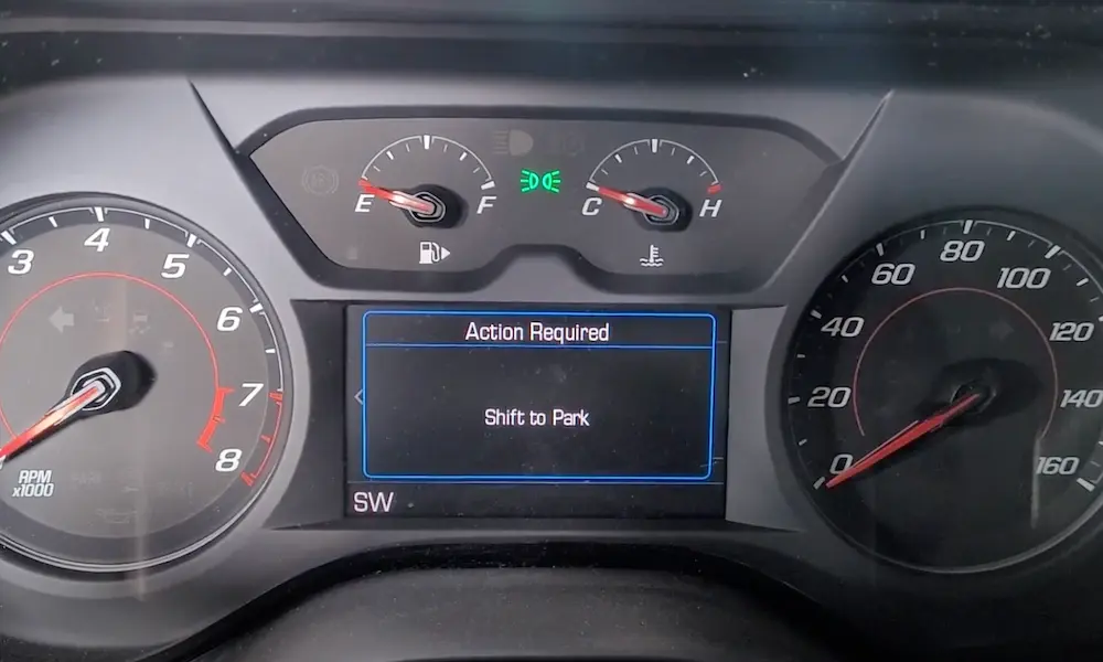
Is your vehicle suddenly sluggish, stuck in a single gear, or refusing to go above a certain speed? You might be experiencing limp mode—your car’s self-preservation mechanism. When critical sensors detect potential problems, your vehicle deliberately limits performance to prevent expensive damage. Let’s dive into the sensors responsible for triggering limp mode and how to address these issues before they leave you stranded.
Understanding Limp Mode and Its Triggers
Limp mode (also called “fail-safe” or “safe mode”) is your vehicle’s emergency response system. When the engine control module (ECM) or transmission control module (TCM) detects potentially damaging conditions, it restricts engine power, limits gear selection, and caps your speed—typically between 30-45 mph.
While frustrating, this protection mechanism is actually saving you from potentially catastrophic (and expensive) engine or transmission damage. Knowing which sensors trigger limp mode can save you time and money during diagnosis.
Engine Management Sensors That Cause Limp Mode
Mass Air Flow (MAF) Sensor
The MAF sensor measures incoming air volume and density so your engine can calculate the perfect fuel ratio. When it fails, your engine can’t maintain the proper air-fuel mixture.
Common MAF failure symptoms:
- Sudden power loss and sluggish acceleration
- Engine stalling or rough idle
- Black smoke from exhaust
- Check engine light with P0100-P0103 codes
- Immediate limp mode activation
Your MAF sensor can fail from dirt buildup, oil contamination from poor air filters, or electrical issues. Sometimes a simple cleaning with MAF sensor cleaner resolves the problem, but severely contaminated sensors need replacement.
Throttle Position Sensor (TPS)
The throttle position sensor tells your ECM how far you’re pressing the gas pedal, directly affecting fuel delivery and ignition timing. Modern vehicles use electronic throttle control with redundant TPS sensors for safety.
Signs of TPS failure include:
- Hesitation during acceleration
- Unpredictable engine behavior
- Transmission shifting problems
- Engine stalling at idle
- P0120-P0123 trouble codes
TPS sensors typically fail when their internal resistive strips wear out, creating “dead spots” during operation. This confuses your ECM, which responds by triggering limp mode to prevent potential damage.
Critical Position and Speed Sensors
Crankshaft Position Sensor
The crankshaft position sensor is arguably the most important sensor for engine operation. It tracks the position and rotational speed of your crankshaft, providing essential data for fuel injection timing and ignition control.
When your crankshaft sensor fails:
- Engine may crank but won’t start
- Vehicle stalls unexpectedly
- Transmission gets stuck in a single gear
- Complete loss of power
- Check engine light with P0335-P0338 codes
Without accurate crankshaft position data, your ECM can’t properly time ignition and fuel delivery, often resulting in immediate limp mode or even complete engine shutdown to prevent damage.
Camshaft Position Sensor
Working alongside the crankshaft sensor, the camshaft position sensor monitors valve timing, especially important in variable valve timing engines.
Symptoms of camshaft sensor failure:
- Engine jerking and random power surges
- Poor acceleration
- Hard starting
- Engine misfires
- P0340-P0349 error codes
Modern engines often have multiple camshaft sensors, and failure of any single one can trigger limp mode to protect your engine from potential valve and piston collision damage.
Transmission Speed Sensors
Transmission speed sensors monitor input and output shaft speeds, allowing your transmission control module to calculate gear ratios and perform proper shifts.
When speed sensors fail:
- Transmission shifts erratically
- Vehicle gets stuck in a specific gear
- Speedometer operates inconsistently
- Delayed or harsh shifting
- P0715-P0722 error codes
Your transmission control module requires accurate speed sensor data to determine shift timing. Without it, the TCM engages limp mode to prevent transmission damage from improper shifting.
Pressure and Temperature Sensors
Manifold Absolute Pressure (MAP) and Boost Pressure Sensors
The MAP sensor measures air pressure in your intake manifold, while boost pressure sensors monitor turbocharger output. These are critical for fuel mixture calculation and boost control.
MAP/boost sensor failure symptoms:
- Loss of turbocharger performance
- Engine running rich or lean
- Reduced power and acceleration
- Poor fuel economy
- P0105-P0110 or P0237-P0238 codes
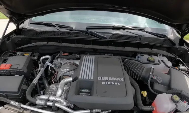
These sensors are particularly important in turbocharged and diesel engines. Improper boost control can cause engine damage from detonation or excessive cylinder pressure, triggering limp mode as a protective measure.
Fuel Rail Pressure Sensor
The fuel rail pressure sensor monitors your fuel system’s pressure, critical for direct injection and common rail diesel engines.
Fuel pressure sensor issues cause:
- Hard starting
- Stalling and rough idle
- Significant power loss
- Poor fuel economy
- P0087-P0089 trouble codes
High-pressure fuel systems rely on precise pressure control. When the sensor fails, your ECM can’t maintain proper injection timing or quantity, activating limp mode to prevent fuel system damage.
Engine Coolant Temperature Sensor
The coolant temperature sensor monitors engine temperature, helping your ECM adjust fuel mixtures and control cooling fans.
Symptoms of coolant sensor failure:
- False overheating warnings
- Poor cold-start performance
- Excessive fuel consumption
- Cooling fan operation problems
- Temperature-related trouble codes
Some vehicles, particularly certain Ford models, have known issues with coolant temperature sensors triggering limp mode. The ECM activates limp mode to protect against potential overheating damage when it receives incorrect temperature data.
| Sensor Type | Common Trouble Codes | Primary Function | Limp Mode Likelihood |
|---|---|---|---|
| MAF Sensor | P0100-P0103 | Measures incoming air | Very High |
| Crankshaft Sensor | P0335-P0338 | Engine timing reference | Very High |
| TPS | P0120-P0124 | Monitors throttle position | High |
| MAP/Boost Sensor | P0105-P0110, P0237-P0238 | Measures intake pressure | High (turbocharged) |
| Camshaft Sensor | P0340-P0349 | Valve timing reference | High |
| Trans Speed Sensors | P0715-P0722 | Measures shaft speeds | High |
| Fuel Pressure | P0087-P0089 | Monitors fuel system pressure | Medium-High |
| Coolant Temp | P0115-P0119 | Engine temperature | Medium |
| O2/Air-Fuel | P0130-P0175 | Exhaust oxygen content | Low-Medium |
Diagnosing Sensor-Related Limp Mode
Using an OBD-II Scanner
The first step in diagnosing limp mode is retrieving diagnostic trouble codes using an OBD-II scanner. This provides critical information about which systems are malfunctioning.
- Connect your scanner to the OBD-II port (usually under the dashboard)
- Turn the ignition to the “on” position without starting the engine
- Retrieve and record all stored and pending codes
- Check live data streams for abnormal sensor readings
- Research the specific codes for your vehicle make and model
While basic code readers can identify general problems, professional-grade scanners provide more detailed information, including manufacturer-specific codes and access to transmission control modules.
Testing Sensors with a Multimeter
A digital multimeter is essential for verifying sensor operation. Most automotive sensors can be tested for proper resistance, voltage output, or signal frequency.
Key multimeter tests include:
- Resistance testing: Disconnect the sensor and measure resistance between terminals. Compare to specifications in your service manual.
- Voltage testing: With the sensor connected and ignition on, measure reference voltage and output voltage.
- Signal testing: For digital sensors, test for proper frequency or pulse width modulation signals.
Remember that specifications vary significantly between vehicle makes and models, making service manual references essential for accurate diagnosis.
Visual Inspection Is Critical
Many sensor failures result from physical damage, contamination, or wiring problems that can be identified through careful visual inspection.
Look for:
- Damaged connectors or corroded terminals
- Cracked sensor housings
- Oil or coolant contamination
- Loose mounting hardware
- Chafed or damaged wiring
- Vacuum leaks around sensors
Physical damage from engine vibration, heat, or impact is a common cause of sensor failure, particularly in high-mileage vehicles. Proper routing and securing of wiring harnesses can prevent many sensor-related limp mode incidents.
Multiple Sensor Integration Issues
Modern vehicles often experience limp mode due to cascading sensor failures or system integration issues rather than single sensor problems. The ECM continuously monitors sensor inputs for consistency and correlation.
Common integration scenarios include:
- Crankshaft and camshaft sensor correlation errors
- MAP sensor and MAF sensor disagreements
- Multiple transmission speed sensor failures
- Boost control system sensor conflicts
When multiple sensors fail simultaneously, diagnosis becomes more complex and may require systematic testing of each component. Some intermittent failures only appear under specific operating conditions, making road testing essential.
Preventing Sensor-Related Limp Mode
Preventing sensor-related limp mode involves proactive maintenance and system monitoring. Regular inspection and cleaning can extend sensor life and prevent unexpected failures.
Preventive measures include:
- Regularly replacing air filters to protect MAF sensors
- Maintaining proper coolant levels and quality
- Using quality fuel and fuel additives
- Keeping electrical connections clean and tight
- Following manufacturer-recommended service intervals
When replacement is necessary, invest in quality parts. OEM or equivalent sensors provide better reliability than bargain alternatives. Poor-quality sensors often lead to recurring problems and repeated limp mode episodes.
| Maintenance Task | Frequency | Sensors Protected |
|---|---|---|
| Air Filter Replacement | 15,000-30,000 miles | MAF sensor |
| Fuel System Cleaning | 30,000-60,000 miles | Fuel pressure sensors, injectors |
| Coolant Flush | 30,000-60,000 miles | Temperature sensors |
| Electrical Connection Cleaning | Yearly inspection | All sensors |
| Vacuum Line Inspection | Yearly inspection | MAP/boost sensors |
Addressing sensor issues promptly prevents the cascading failures that often lead to limp mode activation. Paying attention to early warning signs—like minor performance issues, occasional warning lights, or unusual behavior—can help you catch sensor problems before they trigger full limp mode.
Understanding Sensor Interactions
The modern vehicle is a complex network of interconnected systems. Sensors don’t operate in isolation—they’re part of a comprehensive monitoring system. Understanding these relationships helps with accurate diagnosis.
For example, a failing crankshaft position sensor might first appear as a transmission issue because the TCM uses engine speed data for shift timing. Similarly, a boost pressure sensor failure might initially present as poor fuel economy before triggering limp mode.
By recognizing these sensor relationships, you can more effectively diagnose the root cause of limp mode rather than treating symptoms. This approach saves time, money, and prevents repeated failures.
When your vehicle enters limp mode, take it as a warning that something needs attention. Rather than repeatedly clearing codes and continuing to drive, address the underlying sensor issues promptly to prevent more serious and expensive damage.