Thinking about tackling a 4L80E transmission rebuild? It’s a serious job — but it’s absolutely doable if you know what you’re doing. This guide walks you through every critical stage, from teardown to torque specs to road testing. Stick around to the end, because the details in the final sections can make or break your build.
What Makes the 4L80E Worth Rebuilding
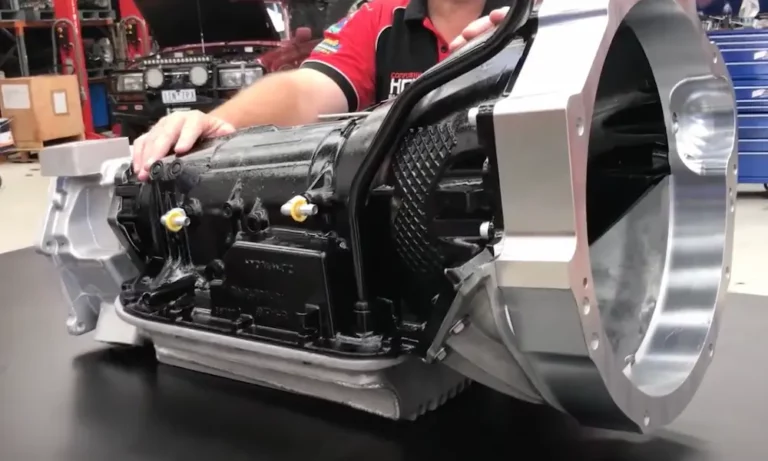
The 4L80E is no ordinary automatic transmission. GM introduced it in 1991 as the electronically controlled successor to the legendary TH400. It handles up to 440 ft-lbs of engine torque and 885 ft-lbs of output torque — numbers that make it the go-to unit for heavy trucks, diesel vans, and high-performance builds.
It even found its way into Rolls-Royce, Bentley, and Aston Martin vehicles. If it’s good enough for a Bentley, it’s good enough for your truck.
The name tells the whole story: 4-speed, Longitudinally mounted, rated for 8,000 lbs. GVWR, Electronically controlled. It ran in production through 2009 and remains one of the most rebuildable transmissions on the market.
Gear Ratios at a Glance
| Gear | Ratio | Purpose |
|---|---|---|
| 1st | 2.48:1 | Heavy load starts, maximum torque |
| 2nd | 1.48:1 | Balanced acceleration |
| 3rd | 1.00:1 | Direct drive |
| 4th | 0.75:1 | Overdrive, fuel savings |
| Reverse | 2.07:1 | Trailer maneuvering |
Know Your Year Before You Buy Parts
This is the #1 mistake people make with a 4L80E transmission rebuild. Parts don’t always interchange across years, and buying the wrong kit costs you time and money.
1991–1996 Units
Early units have cooling lines at the front of the case. They also use a vented Bosch EPC solenoid with a specific valve body configuration. These early designs had a known lubrication problem — restricted oil flow to the rear gear train caused overheating under heavy loads.
1997 Redesign
In 1997, GM moved the return cooler line to the rear of the case to feed the center support directly. This required a new case casting, pump, center support, and valve body. Pre-1997 and post-1997 parts don’t interchange without major hydraulic circuit modifications.
1999+ Planetary Updates
Starting in 1999, GM thickened the planetary pinions by about 10% for more torque capacity. This change required a 0.041-inch shim in the gear train and a modification to the sun gear shaft. Miss this during reassembly and you’ll have a misaligned gear train.
Tools You Actually Need
Don’t attempt a 4L80E rebuild with just hand tools. Here’s what a proper build requires:
Measuring Tools:
- Dial indicator with magnetic base (input shaft end play)
- Feeler gauges (clutch pack clearances)
- Digital calipers or micrometers (shim selection, worn plate measurement)
- Inch-pound AND foot-pound torque wrenches
Transmission-Specific Tools:
- Pump puller — never pry between the pump and the aluminum case. You’ll crack it.
- Snap ring pliers in multiple sizes
- Lip seal protectors — these prevent rubber seals from getting cut during piston installation
- Bushing driver and blind hole puller set
Keep your workspace spotless. A single piece of debris in the valve body can stick a valve and ruin the whole build.
Teardown: The Right Order Matters
External Disassembly First
Start by pulling the torque converter — it’s heavy, so watch your fingers. Remove the Input Speed Sensor (ISS), Output Speed Sensor (OSS), and the Digital Transmission Range (DTR) sensor from the manual shaft.
Pull the 17 pan bolts and drop the pan. Inspect it carefully. A little fine metallic glitter is normal wear. Large metal chunks or “clutch mud” mean hard part failure — expect to replace planetary sets or bearings.
Valve Body Removal
Disconnect the internal wiring harness from the shift solenoids, EPC, TCC, and Pressure Switch Manifold (PSM). These connectors get brittle with heat cycles — be gentle. Remove the valve body as one unit, then pull the separator plate and gaskets.
Collect all eight check balls from the case and separator plate. These act as one-way valves for specific hydraulic circuits. Lose one, and you’ll have a mystery leak.
Core Internal Disassembly
Once the valve body is off, pull the pump with a specialized puller. Behind it sits the overdrive section — fourth clutch assembly, overrun clutch, and overdrive planetary set.
The fourth clutch bolt on the underside of the case must come out first. It’s a torque-to-yield bolt — replace it every time, no exceptions.
Next come the forward and direct clutch drums. Check the drum surfaces where Teflon sealing rings ride. Grooves in these areas cause hydraulic leaks and 3rd gear slip or reverse loss.
Remove the center support (on 1997+ units, pull the rear cooler line fitting first), then extract the remaining gear train.
Inspection: What to Keep and What to Toss
Planetary Gear Sets
Planetary gear sets take serious abuse. Check for:
- Blue or black discoloration — extreme heat, steel is compromised
- Pointed gear teeth instead of squared — worn beyond spec
- Pitting or scuffing on tooth faces — early surface fatigue
- Excessive planet gear wobble — worn pinion pins, replace the whole carrier
Bushings
Worn bushings let shafts wobble, which kills the Teflon rings and wears drum bores. Key spots to check:
- Stator support bushings — worn ones cause direct drum wobble and 3rd gear clutch failure
- Rear case bushing — if this is worn, expect driveline vibration and rear seal failure
Friction and Steel Plates
Replace all friction plates and rubber seals during every rebuild. Steel plates can be reused only if they’re flat and show no blue “hot spots.” Those discolored circles have different friction characteristics and will chew through your new frictions fast.
Performance Upgrades Worth Doing
If you’re building for performance or heavy towing, these mods are worth every minute.
The Internal Dual Feed Mod
Stock hydraulics only use half the direct clutch apply area in 3rd gear. The dual feed mod doubles that holding capacity, which prevents 3rd gear slip in high-power applications. Here’s the process:
- Remove the center lip seal from the direct clutch apply piston
- Remove the second sealing ring from the top of the center support
- Plug the case passage that separates the two direct clutch apply circuits
Fix the AFL Valve
The Actuator Feed Limit (AFL) valve wears its aluminum bore over time. That wear creates a hydraulic leak that starves the shift solenoids and EPC solenoid — resulting in soft shifts or gear hunting. Install a sleeved AFL valve kit (Transgo or Sonnax) and fix it permanently.
Line Pressure Upgrades
For high-torque applications, install an oversized boost valve in the pump — the Sonnax LB1 is a proven choice. Also consider:
- Drilling a 0.055″–0.067″ hole in the pump cover between line pressure and converter charge passages
- Opening the separator plate orifices: 0.078″ for 2nd gear, 0.093″–0.110″ for 3rd and 4th gears
Setting Clearances: This Is Where Rebuilds Win or Lose
End Play Specifications
Set rear end play first, adjusted by selecting the 3-tab selective washer at the back of the case. Then set front end play by changing the selective washer behind the pump.
| Measurement | Target Range | Adjustment |
|---|---|---|
| Rear End Play | 0.005″–0.025″ | Selective washer, rear case |
| Front End Play | 0.005″–0.025″ | Selective washer behind pump |
Ideally, front end play should run slightly larger than rear (e.g., 0.012″ front, 0.008″ rear) to handle the forward thrust load during shifts.
Clutch Pack Clearances
Measure every clutch pack with a feeler gauge. Adjust with different thickness pressure plates or snap rings.
| Clutch Pack | Target Clearance | What Goes Wrong |
|---|---|---|
| Forward | 0.040″–0.055″ | Too tight = drag; too loose = harsh garage shift |
| Direct | 0.050″–0.065″ | Too tight = 3rd tie-up; too loose = 2-3 flare |
| Intermediate | 0.040″–0.107″ | Critical for 1-2 shift quality |
| Overdrive | 0.040″–0.100″ | Prevents 4th gear drag |
| 4th Clutch | 0.050″–0.070″ | Controls 3-4 shift quality |
Air check every clutch pack at 40 PSI before final assembly. If the piston doesn’t move, something’s wrong with the seal.
Torque Specs: Don’t Wing It
Steel bolts going into aluminum strip easily. Use a torque wrench on everything. Apply thread locker to critical internal bolts like the center support and parking pawl bolts.
| Component | Torque |
|---|---|
| Case Center Support Bolt | 29 ft-lbs |
| Pump to Case Bolts | 18 ft-lbs |
| Valve Body to Case Bolts | 97 in-lbs |
| Transmission Pan Bolts | 18 ft-lbs |
| Solenoid to VB Screws | 71 in-lbs |
| Fourth Clutch Screw | 12 ft-lbs |
| Transmission to Engine | 32 ft-lbs |
| Flexplate to Converter | 32 ft-lbs |
Torque valve body bolts from the center outward to prevent the separator plate from warping.
Torque Converter Installation
A misaligned converter destroys the pump within seconds of startup. Don’t rush this step.
Add about one quart of ATF to the converter before installation. Push it onto the input shaft and rotate it — you should feel three distinct clicks as it engages the input shaft splines, stator support splines, and pump drive flats.
Correct seating depth is 1.030 inches (±0.050″) from the bellhousing face to the converter mounting pads. If you’re measuring 0.750″, it’s not seated — don’t bolt it up.
Once the transmission is on the engine, check the pull-up gap between the converter pads and flexplate. It should be 1/16″ to 1/8″. If it’s over 3/16″, add shims between the flexplate and converter pads. Skip this and you’ll strip the pump drive flats.
Fluid, Startup, and Road Testing
Fluid Requirements
Use DEXRON VI for all 4L80E applications. It handles heat better than DEXRON III and maintains more consistent viscosity. Total capacity with a stock pan is approximately 13.5 quarts.
Startup Procedure
- Add 6–7 quarts before starting the engine
- Start and immediately add fluid while idling
- Cycle the shifter through all positions — P, R, N, D, 2, 1 — holding 3 seconds in each
- Check final fluid level at operating temperature (180°F–200°F)
Adaptive Learning
The PCM will adjust line pressure and shift timing over the first several miles. Shifts might feel slightly odd at first — that’s normal. Run 10–15 full shift cycles through all four gears, and the computer will calibrate itself to the new clutch clearances.
Post-Rebuild Troubleshooting
Even a solid build can have teething issues. Here’s a quick reference:
| DTC Code | Problem | Fix |
|---|---|---|
| P1870 | Transmission slipping | Check clutches; inspect TCC bore |
| P0741 | TCC performance | Inspect converter or TCC solenoid |
| P0748 | EPC circuit fault | Check wiring harness and EPC resistance |
| P0753 | 1-2 solenoid circuit | Verify connector and solenoid (20–40 ohms) |
| P0218 | Overtemperature | Flush cooler lines, check for restriction |
- Harsh 1-2 shift? Check the 1-2 accumulator valve or a disconnected EPC solenoid
- 3rd gear flare? Leak in the direct clutch circuit or worn center support bushing
- No 4th gear? Bad 3-4 shift solenoid or a faulty Engine Coolant Temperature sensor blocking overdrive
Long-Term Maintenance
A well-built 4L80E will last hundreds of thousands of miles if you treat it right:
- Change fluid and filter every 30,000–50,000 miles — more often if you tow constantly
- Install an external transmission cooler — heat kills friction material and seals faster than anything else
- Pay attention to shift feel — a soft shift today can become a slipped clutch next month
The 4L80E transmission is genuinely one of the toughest automatics ever built. Rebuild it right, maintain it properly, and it’ll outlast the truck it’s bolted to.