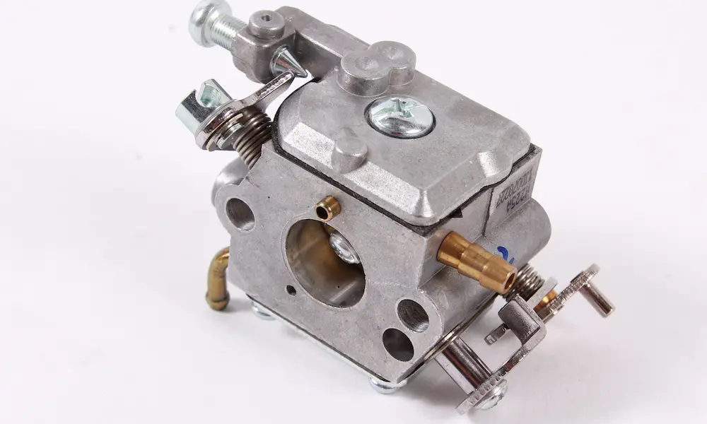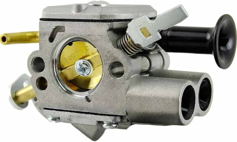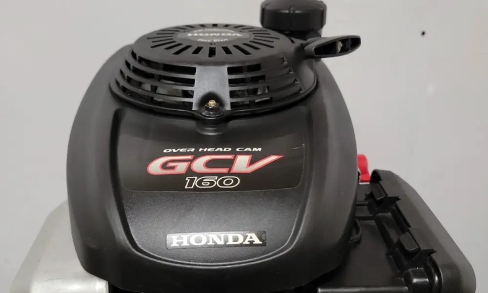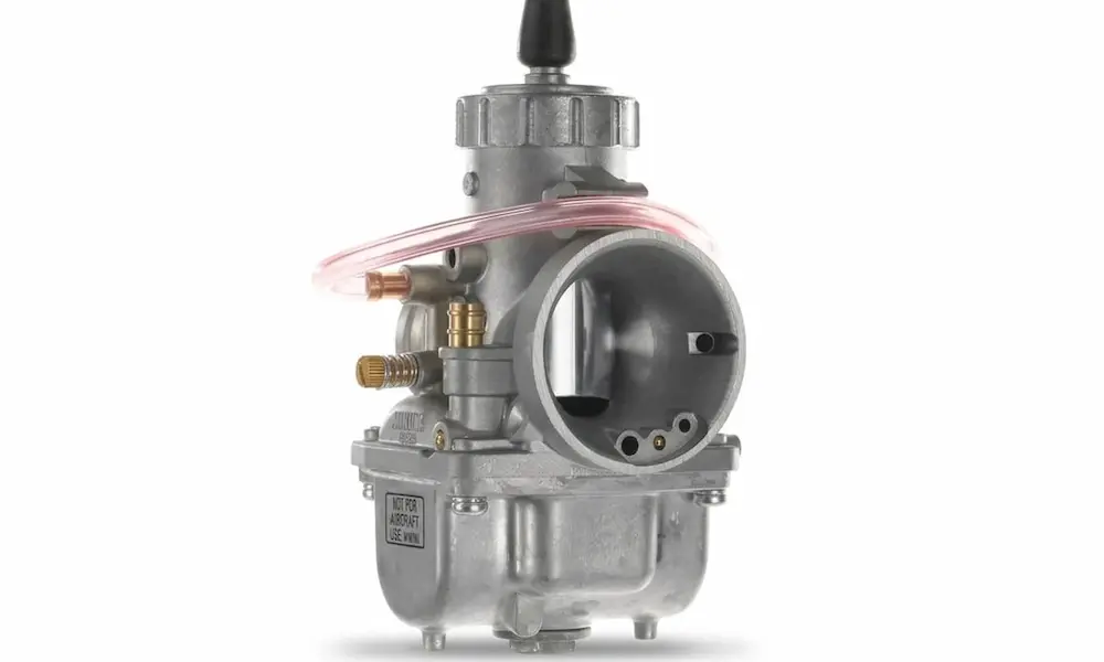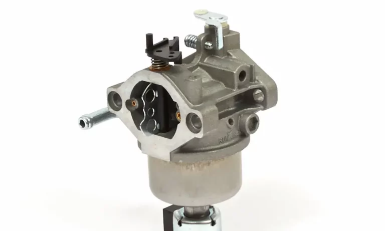
A Briggs and Stratton carb diagram turns that mystery box bolted to your engine into something you can actually read. It labels every jet, gasket, spring, and plug, so you know what you’re looking at before you grab a wrench. This guide walks you through the common diagrams, explains what each part does, and shows you how to use that layout to fix surging, flooding, and no-start problems. Read to the end and you’ll diagnose a clogged circuit by symptom alone.
What a Briggs and Stratton Carb Diagram Actually Shows
It’s an exploded view, not a photo. Every component sits pulled apart along a dashed assembly line, tagged with a reference number, an OEM part number, and a quantity. That’s it. No guessing which screw goes where.
The value comes from precision. Carburetors aren’t single parts. They’re assemblies of dozens of tiny, matched components, and each one has an exact job. Swap in the wrong jet or a sloppy aftermarket gasket, and you’ve changed the air-fuel ratio the factory spent months calibrating.
Find Your Engine Numbers First
Your diagram only applies to your engine. Briggs and Stratton stamps a Model, Type, and Code number directly into the metal of the blower housing, the muffler heat shield, or the overhead valve cover.
Those numbers unlock the correct diagram. A model like 130292 with a specific type code points to one exact illustrated parts list, covering everything from the carburetor body to the idle gallery plugs. You can pull the official document straight from the Briggs & Stratton manuals and parts list page, or look up the diagram visually through a genuine Briggs & Stratton parts lookup.
Don’t skip this step. Ordering a “close enough” part wastes more time than finding the right number.
How Your Carburetor Pulls Fuel (The 30-Second Version)
The whole system runs on a pressure difference. On the intake stroke, your piston drops and creates a low-pressure void in the cylinder. Atmospheric air rushes in to fill it.
That air squeezes through a narrowed throat called the venturi. When air speeds up, its pressure drops. That low-pressure pocket is what pulls liquid fuel out of the bowl and into the airstream — the basic mechanism behind every Briggs and Stratton carburetor diagram.
Fuel doesn’t travel alone, though:
- The main jet meters how much liquid fuel enters the system.
- The emulsion tube is a perforated brass or plastic cylinder that fuel climbs through.
- The high-speed air bleed feeds air into that tube, whipping fuel into a froth.
- That pre-aerated froth hits the venturi and shatters into a fine mist.
Liquid gasoline won’t burn. Mist will. That’s the entire trick.
Decoding the Diagram: Parts You’ll Actually Touch
Here’s a quick reference from a typical Briggs and Stratton 130292-series parts breakdown. Reference numbers match what you’ll see printed on the exploded view.
| Ref # | Part # | Component | What It Does |
|---|---|---|---|
| 90 | 498298 | Carburetor Assembly | The complete fuel-mixing body |
| 96 | 691743 | Throttle Valve | Disc that controls airflow into the intake, setting engine speed |
| 97 | 692325 | Throttle Shaft | Spindle the throttle plate mounts to, linked to the governor |
| 108 | 491177 | Choke Shaft Kit | Operates the choke plate for cold starts |
| 118 | 691777 | Needle Valve | Conical tip that seals against fuel flow to set bowl level |
| 127 | 691742 | Welch Plug | Stamped disc sealing drilled access holes in the idle galleries |
| 149 | 691592 | Needle Valve Spring | Keeps tension on the needle so it seats firmly |
| 152 | 691783 | Friction Spring | Stops vibration from moving adjustment screws |
| 121 | 495606 | Overhaul Kit | Every gasket, seal, and wear part you need for a rebuild |
Match those numbers to your own diagram before ordering. Part numbers vary across models, even when the carburetor looks identical from the outside.
Which Carburetor Is Sitting on Your Engine?
Three families show up on Briggs and Stratton engines. Knowing yours tells you which page of the diagram to trust.
Float-Style: Nikki and Walbro LMT
Most modern engines use these, from push mowers up to V-twin riders. A float bowl hangs under the main body.
Inside, a hinged float rides on the fuel level. As fuel rises, the float lifts an inlet needle with a synthetic rubber tip, sealing off the seat. The engine burns fuel, the float drops, and the cycle repeats. Hundreds of times a minute.
Two suppliers dominate:
- Walbro LMT — often stamped with “LMT” right into the aluminum body. Older versions had fully adjustable idle screws and screw-in jets. Later ones use fixed, pressed-in jets sealed with ball plugs or tamper-proof caps to meet federal rules. The Walbro diaphragm service manual is worth having on your bench.
- Nikki — found on many single and twin-cylinder OHV engines. The main jet and emulsion tube sit in a central pedestal dropping into the bowl. Those pedestal O-rings are a common failure point. When they harden or shrink from heat cycling, raw fuel bypasses the jet and floods the engine.
Fuel level in the bowl is everything. Too high and you get black smoke, fouled plugs, and washed cylinder walls. Too low and you get surging, scorching head temperatures, and pre-ignition damage.
Tank-Mounted: The Pulsa-Jet
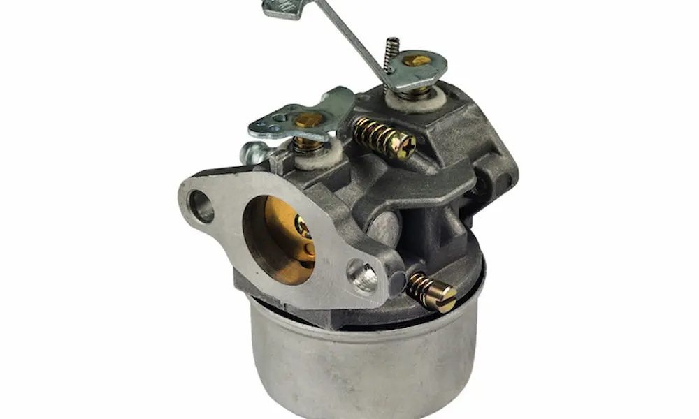
Millions of older 3 to 5 HP flathead engines run this design, and it’s genuinely clever. The carburetor bolts to the top of a fuel tank, so gravity works against it.
Instead of a float, a flexible diaphragm pump sits between the carburetor body and the tank. Crankcase pressure pulses flex that diaphragm against a calibrated spring, pulling fuel up a long pickup tube from the deep main reservoir into a shallow upper cup.
Here’s the neat part: the pump always delivers more than the engine burns. The cup overflows continuously, spilling back into the tank. That constant overflow keeps the fuel level around the main jet perfectly stable — a float bowl without a float. It’s why the primer bulb works and why there’s no needle valve to stick.
Common failures follow the design. The classic symptom is an engine that fires on sprayed fuel then dies instantly. The diaphragm has stiffened, aged, or ruptured. Replace it (part 795083 is common), preload the internal spring, and tighten the screws in an intermittent star pattern so you don’t warp the casting. A step-by-step Pulsa-Jet rebuild walkthrough shows the sequence clearly.
Also check the tiny fixed low-speed jet screwed into the base where it meets the tank. It clogs easily and hides from casual inspection. And since the pulse port depends on a large gasket sealing body to tank, any warp in the base kills the vacuum signal and starves the engine.
Legacy: Flo-Jet Series
Long before Nikki and Walbro, Briggs and Stratton built their own Flo-Jets — Small One-Piece, Large One-Piece, and Two-Piece Updraft. These are float-feed units with adjustable orifice needles for both idle and main circuits. The Small One-Piece has its adjustment needles on top of the body. The Large version puts the main adjustment needle below the bowl.
Servicing them takes specific tools. Extracting the emulsion tube requires Briggs and Stratton Tool #19062, and specific L-head models need Tool #19280. On Large One-Piece Choke-A-Matic models, you must pull a choke plate stop pin before the venturi slides out. The official Flo-Jet disassembly manual spells out every step. Improvise here and you’ll shear a brass tube.
Cold-Start Systems You’ll See on the Diagram
Cold fuel refuses to vaporize. It condenses on cold intake walls and never reaches the cylinder. So every diagram includes some enrichment hardware.
Primer Bulb Systems
Many walk-behind mower carbs skip the choke plate entirely. You press the rubber bulb three times, and it acts as a tiny air pump. That pressurized air gets routed into the sealed float bowl, forcing fuel up through the emulsion tube and spraying it raw into the venturi.
No choke cable, no linkage, lower cost, lower cold-start emissions. When it fails, look for a cracked bulb, a torn bowl gasket leaking your pressure to atmosphere, or a clogged main nozzle.
ReadyStart Auto Choke
ReadyStart handles choking for you with three parts working in sequence:
- A cold-closure spring holds the choke plate shut while the engine is off and cold.
- A pneumatic air vane catches the breeze from the spinning flywheel fins and forces the choke open the moment the engine fires.
- A bimetallic thermostat near the muffler expands with heat, extending a rod that locks the choke fully open once the engine warms up.
That thermostat rod is the one laying horizontally on the right side of the linkage. Debris binding the linkage, or a broken closure spring, causes hard cold starts. Black smoke and surging after warm-up means the thermostat stopped expanding and left the choke closed on a hot engine. Briggs & Stratton explains the auto choke behavior on its support pages, and the linkage geometry is fussy enough that a photo-labeled auto choke linkage diagram earns its keep.
Small Parts, Big Problems
Welch Plugs
You can’t cast intersecting internal galleries, so manufacturers drill them from outside and seal the holes with domed metal discs. A punch flattens each dome, expanding it so the edge bites into the aluminum casting. Permanent, airtight seal.
When idle and progression galleries clog, your engine surges at idle or only runs with the choke partly on. Those circuits live behind the welch plugs. The fix is to pierce and extract the old plug with an awl, clean the microscopic ports with solvent, tag wire, or ultrasonic cavitation, then install a fresh plug. A thin smear of fuel-resistant enamel around the perimeter prevents vacuum leaks. Seeing a welch plug removal in action makes the process click.
The Anti-Afterfire Solenoid
Kill the key on a big riding mower and the engine keeps spinning from inertia. It pumps unburned fuel straight into a scorching muffler. The result is a gunshot bang called afterfire. Briggs & Stratton’s own explanation of backfire and afterfire makes the cause obvious.
The solenoid threads into the bottom of the float bowl and doubles as the bowl nut. Turn the key on, and 12 volts retract a pintle, opening the main jet. Turn it off, and the spring snaps the pintle shut. No fuel, no bang.
Diagnosing it is simple. Key on, listen for a click at the bowl. No click? Check voltage at the spade connector. Here’s the trap: the solenoid grounds through its own casing into the carburetor body and then the engine block. A rusty mounting stud or corroded threads breaks that ground, and the solenoid stays dead no matter how good the incoming voltage looks.
Why Today’s Fuel Wrecks Factory Precision
Modern pump gas is oxygenated with ethanol, and that single fact drives more carburetor failures than anything else. Ethanol is hygroscopic — a chemical sponge for moisture in the air. Small engine fuel systems are vented and sit dormant in humid sheds for months.
Once ethanol absorbs enough water, phase separation hits. The ethanol-water mix drops out of suspension, turns heavier than gasoline, and sinks to the lowest point in the system: your float bowl.
| Degradation Type | What’s Happening | What You’ll See |
|---|---|---|
| Phase separation | Moisture absorption passes saturation limits | Corrosive, non-combustible liquid puddled in the bowl; engine won’t start |
| Galvanic corrosion | Acids attack unplated non-ferrous metals like Zamak 5 and magnesium alloys | White powder on aluminum, green verdigris on brass jets and emulsion tubes |
| Varnish buildup | Volatile aromatics evaporate, leaving heavy hydrocarbons | Amber residue permanently clogging idle jets and transfer ports |
| Elastomer breakdown | Solvents attack incompatible synthetic rubbers | Swollen needle tips that flood the engine; brittle, stiff pump diaphragms |
One winter of untreated separated fuel can pit an aluminum bowl deeply and turn a brass emulsion tube bright green. Oklahoma State Extension’s fact sheet on ethanol blends and small engines walks through the chemistry, and Rider Magazine’s look at ethanol and carburetors covers the practical fallout.
Defend yourself. Use a stabilizer with corrosion inhibitors built for ethanol — Star Tron, Sea Foam, Marvel Mystery Oil, or Carb Defender all do the job. Drain the bowl through the brass drain plug before storage. Better yet, run ethanol-free recreational fuel like Rec-90 and skip the whole cycle.
The EPA Angle Nobody Warns You About
Older carbs had spring-loaded idle mixture screws you could tune for altitude, temperature, or engine wear. People tuned them pig rich, and hydrocarbon emissions ballooned. So the EPA’s small equipment emissions regulations pushed manufacturers to fixed, non-adjustable metering jets.
The upside is cleaner air. The downside is zero margin. These engines already run lean by design, at higher head temperatures. A varnish layer narrowing a fixed jet by a fraction of a millimeter pushes it into lean misfire — surging, power loss, and real heat damage. You can’t back out a screw to compensate. You clean it or replace it.
Cleaning Methods That Quietly Destroy Carburetors
Never run stiff wire or welding tip cleaners through a brass jet. This old habit is the fastest way to ruin a carburetor. Steel scratches soft brass and enlarges the precision orifice, permanently altering fuel delivery on an engine that can’t tolerate the change.
Do this instead:
- Submerge dismantled metal parts in an ultrasonic cleaner with heated, non-caustic degreaser. Microscopic cavitation bubbles implode against the casting and reach blind passages no brush can.
- Follow up with aerosolized solvent through a straw nozzle on every port to confirm free flow.
- Replace every O-ring, bowl gasket, and throttle shaft seal. A worn shaft seal lets ambient air bypass the venturi and leans the mixture beyond what any jet can fix.
Reassembly: Torque and Float Height
Before anything goes back on, verify float height. Invert the carburetor body. Older brass or adjustable plastic floats should sit level with the casting. Too high floods the engine. Too low starves it under load. Many modern plastic floats aren’t adjustable, so check the needle tip for a wear ridge and replace it if you find one.
Then torque to spec. Guessing here causes leaks that mimic other problems.
- Carburetor to intake manifold: 100 inch-pounds. Over-tightening warps the aluminum flange and creates vacuum leaks. Under-tightening lets vibration walk the fasteners loose.
- Air cleaner base to carburetor: 25 inch-pounds. Any more strips the soft aluminum threads.
- Carburetor bowl plug or solenoid: 100 inch-pounds. Excess torque crushes the fiber bowl gasket and dumps fuel onto hot engine parts.
Align the intake manifold gasket carefully, and use a calibrated torque wrench. Briggs & Stratton’s rebuild FAQ covers what a proper overhaul kit should include. If you’re working on a Vanguard or other larger platform, the Toro-published service manual for Vanguard OHV engines has factory torque values and linkage specs.
Final Thoughts
A Briggs and Stratton carb diagram is more than a parts list. It’s a diagnostic tool. Once you can look at a surging engine and think “welch plug” or look at a no-start and think “phase separation,” you’ve stopped guessing.
The design has shifted hard over the decades. Adjustable Flo-Jets and diaphragm-driven Pulsa-Jets gave way to fixed-jet Nikki and Walbro units built to satisfy emissions rules. Meanwhile, ethanol-blended fuel turned the inside of a float bowl into a hostile chemical environment for Zamak castings and rubber seals. The tolerance for neglect is basically gone.
So treat your diagram like the manual it is. Match your engine numbers, order exact parts, clean with chemicals and ultrasound instead of wire, torque every fastener, and manage your fuel before storage ever becomes a problem. Do that, and the carburetor stays the simple, precise instrument it was built to be.