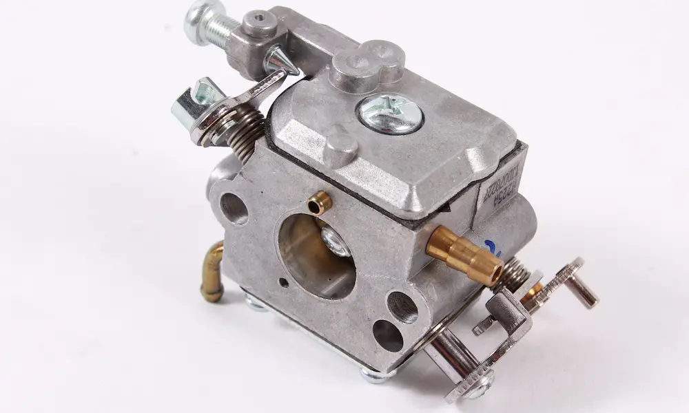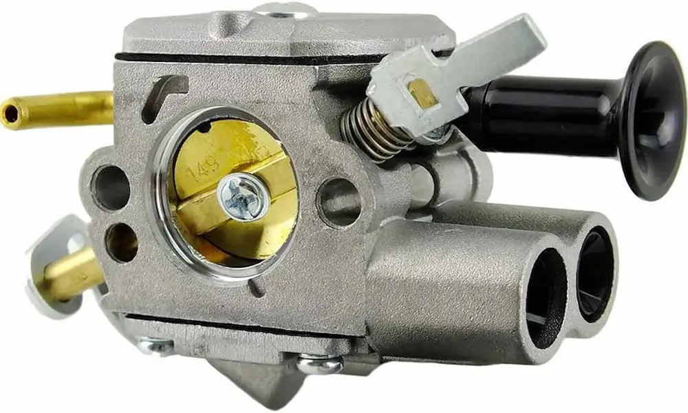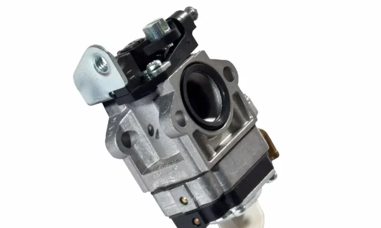
Staring at a Walbro carb diagram feels like reading a math test in a language you don’t speak. Tiny numbered parts, weird names, no clue what half of it does. But once you get the logic behind it, the whole thing clicks into place fast. This guide breaks down every piece on the diagram, shows you how fuel actually moves through the carb, and helps you spot problems before you tear anything apart.
Why the Walbro Carb Diagram Looks So Complicated
Walbro diaphragm carburetors don’t use gravity or a float bowl. That’s actually the whole point of the design. Old-school carbs needed to stay upright, or fuel would spill out. Walbro fixed that problem back in the 1950s with a pump-and-diaphragm setup that works in any position, even upside down.
That flexibility comes at a cost: more moving parts crammed into a tiny aluminum body. The diagram looks busy because the carb is doing three jobs at once. It pumps fuel, regulates pressure, and mixes fuel with air. Once you separate those three systems in your head, the diagram stops looking like a puzzle.
Breaking Down the Walbro Carb Diagram Piece by Piece
Every Walbro WA and WT series schematic numbers its parts in roughly the same order fuel travels through the carb. Here’s what each numbered component actually does.
| Diagram Part | Name | What It Does |
|---|---|---|
| 1 | Engine Impulse Port | Lets crankcase pressure pulses into the carb to power the pump |
| 2 | Fuel Pump Diaphragm | Flexes with each pulse to physically move fuel |
| 3 | Fuel Inlet Fitting | Where the fuel line from the tank connects |
| 4 | Inlet Check Valve | Opens to pull fuel in during the vacuum pulse |
| 5 | Outlet Check Valve | Pushes fuel forward during the pressure pulse |
| 6 | Filter Screen | Catches dirt before it reaches the needle valve |
| 7 | Inlet Needle Valve | Controls fuel entering the metering chamber |
| 8 | Throttle Valve | Butterfly disc that controls airflow |
| 9-11 | Idle Holes | Feed fuel at idle and during throttle progression |
| 12 | Idle Adjustment Needle | Sets idle fuel volume |
| 13-14 | Metering Lever & Spring | Translate diaphragm movement into needle valve action |
| 15-16 | Vent Hole & Metering Diaphragm | React to vacuum, open the inlet needle |
| 17 | Nozzle Check Valve | Stops air from bleeding backward at idle |
| 18 | High-Speed Needle | Controls fuel at full throttle |
| 19 | Main Nozzle | Delivers fuel at high speed |
| 20 | Choke Valve | Restricts air for cold starts |
Notice the pattern? Fuel gets pulled in (parts 1-6), regulated (parts 7, 13-16), then delivered based on throttle position (parts 9-11 and 18-19). It’s a straight line, not a random mess.
How Fuel Actually Moves Through a Walbro Carburetor
The Walbro service manual breaks the carb into three working systems. Understanding these makes the diagram make way more sense.
The Fuel Pump
Your engine’s crankcase creates alternating pressure and vacuum as the piston moves up and down. That pulse gets routed straight into the carb through a hose or internal channel. It hits the pump diaphragm, which flexes back and forth thousands of times a minute.
Two tiny flapper valves, cut right into the diaphragm, turn that flexing into one-way fuel flow. Vacuum opens the inlet valve and pulls fuel in. Pressure snaps it shut and pushes the outlet valve open, sending fuel toward the metering chamber.
The Metering Chamber
This is where the pressure gets smoothed out. Raw pump pressure is jerky and inconsistent, so the metering diaphragm and a spring-loaded lever bring it down to a steady level that matches outside air pressure.
When the engine needs fuel, vacuum pulls the metering diaphragm inward. That pushes on the metering lever, which lifts the inlet needle off its seat and lets fuel in. Once the chamber fills up, the spring pushes the needle shut again. This happens continuously while the engine runs.
The Venturi and Nozzles
Once fuel sits in the metering chamber at atmospheric pressure, it just needs a path into the airstream. Air rushing through the narrow venturi speeds up and drops in pressure (basic fluid dynamics). That low pressure sucks fuel out of the nozzles and shears it into a fine mist.
At idle, the throttle plate blocks most airflow, so a tiny idle hole does all the work. As you open the throttle, progression holes kick in one at a time to keep fuel matched to the extra air. At full throttle, the main nozzle takes over completely.
Butterfly vs Rotary Valve: Two Different Diagram Styles
Not every Walbro carb diagram looks the same. There are two major airflow designs, and they change how the diagram reads.
Butterfly valve carbs (WA, WT, HDA, HDC series) use a flat disc on a shaft to block or open the airway. These are the most common designs on chainsaws and trimmers. They usually have separate low-speed and high-speed adjustment screws, which makes them easy to tune for altitude or fuel changes, according to Walbro’s technical documentation.
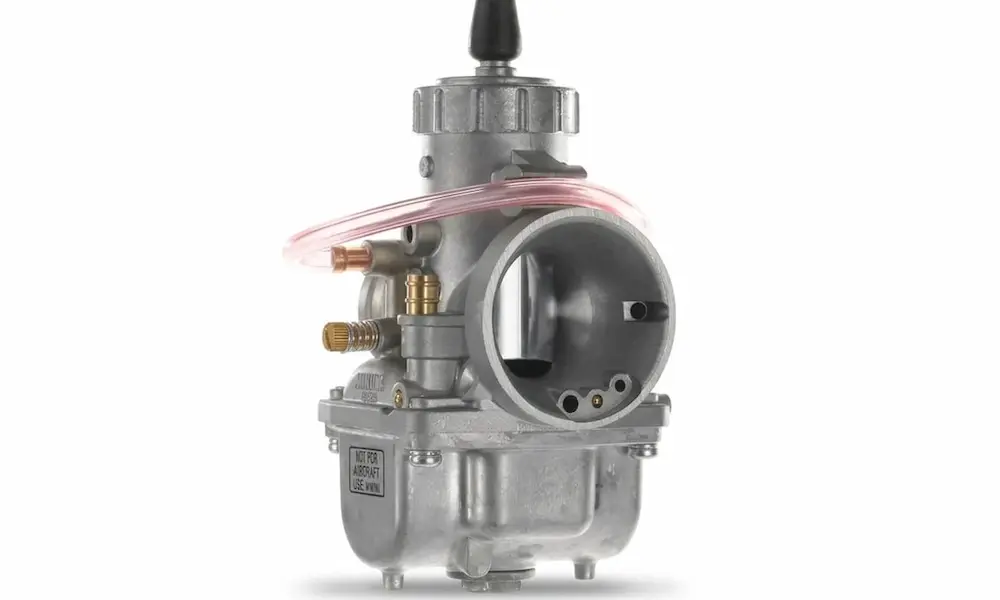
Rotary valve carbs (WY, WYK, WYL series) use a spinning barrel instead of a disc. As the barrel rotates, it opens the airway and simultaneously lifts a tapered needle out of the main jet. This gives super quick throttle response and a smoother airflow path, per Walbro’s rotary carb documentation. Most rotary carbs use fixed jets instead of adjustable screws, which keeps them EPA-compliant and harder to mess with.
Using the Diagram to Diagnose Problems
Once you know what each part does, the diagram becomes a troubleshooting map. Most carb problems fall into two camps: too lean (starving) or too rich (flooding).
| Symptom | Likely Diagram Component | Fix |
|---|---|---|
| Bogs on acceleration, white spark plug | Metering lever set too low, clogged idle holes | Check lever height with a gauge, clear Welch plug channels |
| Won’t pump fuel at all | Pulse line/port blocked | Clear or replace the impulse hose |
| Black smoke, wet spark plug | Metering lever set too high, debris under needle | Reset lever height, flush the needle seat |
| Rough burbling under load | Missing or stuck nozzle check valve | Replace the nozzle assembly |
| Sudden flooding on startup | Torn pump diaphragm or unseated spring | Replace diaphragm, reseat the spring properly |
If you’re chasing a lean condition, check the Walbro HDA series manual for exact idle hole locations on your model. If it’s running rich, a torn diaphragm or bad check valve is usually the culprit, as detailed on the ArboristSite forums where techs troubleshoot this stuff daily.
Gasket Order Matters More Than You’d Think
Here’s a mistake that trips up a lot of DIYers: flipping the gasket stacking order during a rebuild. The pump side and metering side go together in opposite sequences.
Pump side (from the body out): carburetor body, pump diaphragm, pump gasket, cover.
Metering side (from the body out): carburetor body, metering gasket, metering diaphragm, cover.
Get this backward on the metering side, and the diaphragm sits too close to the lever with no clearance. That holds the needle open permanently and floods your engine the second you crank it. The Walbro WT series manual walks through this stacking order in detail if you want to double check your model.
Metering Lever Height and Pop-Off Pressure
These two specs decide whether your carb runs clean or acts up no matter how much you fiddle with the mixture screws.
Metering lever height controls exactly how far the inlet needle opens. Too high, and it floods. Too low, and it starves. Walbro makes gauges (the 500-13 and 500-528) specifically for checking this, and Walbro’s own tech tips page shows the correct process step by step. WA and WT series levers should sit flush with the casting. HDA and larger series need the lever set slightly below the surface.
Pop-off pressure is the amount of pressure it takes to force the needle open. Too low, and the pump floods the chamber unassisted. Too high, and fuel can’t get through fast enough at speed. General targets run between 10 and 25 psi depending on the engine. You’ll need a pressure tester (Walbro 57-21 or similar) and a bit of oil to “wet” the needle for an accurate reading.
Purge Bulb vs Primer Bulb: Clearing Up the Confusion
Quick myth-buster: that clear bulb on your carb isn’t a primer. It’s a purge bulb, and the difference matters.
A real primer bulb squirts raw fuel straight into the engine. Press it too many times, and you flood the cylinder.
A purge bulb works differently. It pushes air out of the carb and back to the tank through a return line, then pulls fresh fuel in when you release it. Since it never sprays fuel into the engine itself, you can’t flood your saw by mashing the purge bulb too many times. It just clears air out of the system so the engine starts faster.
Final Thoughts
A Walbro carb diagram isn’t as scary as it looks once you know the three systems at play: pump, metering chamber, and venturi. Every numbered part fits into that flow. When your saw or trimmer starts acting up, trace the symptom back to the system, check the lever height, verify the pop-off pressure, and make sure your gaskets went in the right order. Most carb problems come down to one of these basics, not some mystery part you’ve never heard of. Keep the diagram handy, work through it one system at a time, and you’ll fix more problems than you break.